Background |
|
The following procedure describes how to adjust the Mshift and Sshift.
Mshift: Parameters are seldom adjusted from the default
value, but if required, adjustments to the imaging origin in the mainscan
can be made by changing the gc mshift parameters.
Sshift: Parameters are calibrated at the factory and
rarely need adjusting. The larger the parameter the more the image shifts
away from the plate's edge detect edge.
|
Procedure
|
|
To calculate the Mshift / Sshift direction do
the following:
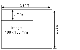
- Send a 100 x 100 mm image via a front end
device.
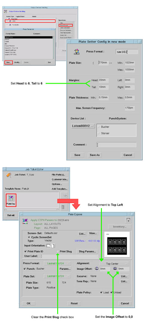
- On the Brisque/Prinergy set the press format
to 6,6
- In the Plate Expose dialog box, do the following:
- Clear the Print Slug checkbox
- Set Alignment to Top
Left
- Set the Image Offset coordinates
to 0,0 as shown:
- Make sure the distance between the edge
of the image and the edge of the plate is 6 mm. If required, use the
Quantum >> Set gc Mshift X parameters to adjust
the offset around the drum axis.
- Make sure the size of the image is 100 mm
when measured from the end of the image until the edge of the plate.
If required, use the Quantum >> Set gc Sshift X parameters
to adjust the image offset along the drum axis.
Reduce X if the image is greater than 100 mm from the
edge.
Increase X, if the image is less than 100 mm from the
edge.
Use a similar calculation for GTO plates. However, GTO plates require
an extra directional test because their plates have separate registration
pins. Use the following parameters to place the image onto a GTO plate
with the required offset. Quantum >> set gc mshiftsmall.
Note:To attain the required direction of between
600 - 800 microns, the mshift valuation must usually be lessened. Mshiftsmall
is used for small plates that have an axis screw of less than 605, according
to the following parameters: Maxsmall = 605
It is not possible to reach the required direction for GTO plates
using Shift separately.
|

