In order for Lotem 800 Quantum to support GTO, the unload
tray must be replaced in the beta machine.
Hardware
Replacing the Unload Tray
The GTO tray has a moving roller that enables you to slip small plates out
of the machine.
To replace the unload tray:
To enable easy access, send the carriage to the middle of the drum.
Open the upper-rear door and remove the upper-rear panel.
Close the Lotem application.
Turn off the air pressure.
Disassemble the unload tray:
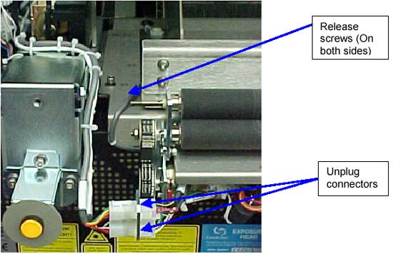
A. Unplug the two connectors on the left side.
B. Loosen the screws that hold the unload tray on both sides.
C. Remove the unload tray by lifting upwards.
Note:Be careful not to let the unload tray damage the head.
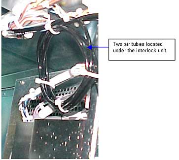
Release the two black air tubes located under the interlock block on the
right-rear side by cutting the plastic bands.
Assemble the GTO tray:
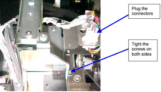
A. Plug-in the two connectors on the right side.
B. Tighten the screws that hold the tray on both sides.
C. Route the wiring behind the interlock box. Note: Be careful not to damage the head.
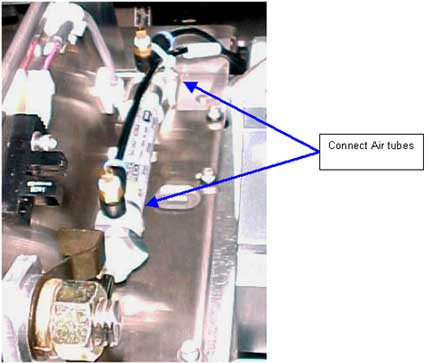
Connect the two air tubes to the pneumatic piston (on the left side).
Make sure that you route them properly (see diagram below).
Check that the H.P. detector wiring on the unload tray is connected.
Turn on the air pressure.
Check the functionality of the upper roller arm by pushing the Lens air
valve. When the valve is active, the upper roller should go down.
Perform mechanical tests:
a. Check that the arm moves up and down smoothly.
The roller should move from upper to lower position in 2-5 seconds.
The roller should move from lower to upper position in 1-2 seconds.
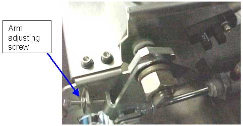
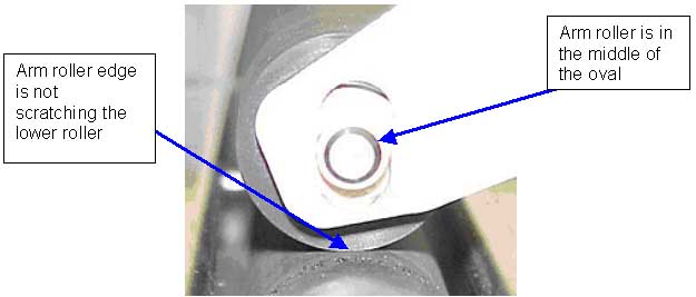
b. Check that the edge of the arm roller holding the upper roller does
not scratch the lower roller when the arm roller is pressed against it.
If necessary, adjust the arm stopper screw. (See picture below.)
c. Check that the upper roller is in the middle of the oval when pressed
against the lower roller.
Assemble the rear panel.
Start the Lotem application.
Software:
This procedure describes the software changes required when adding a GTO unload
tray to the Quantum 800 Beta 5 machine:
Configuring a GTO tray in the Lotem 800 Quantum Beta 5:
In the Lotem main screen, click the Utility button and then select
the Hardware menu. The hardware tree appears.
In the hardware tree, select Lens AirValve and configure
the GTO unload arm as follows:
...\IO OBJECTS\LOCAL 3\SOLENOIDS\Lens Air Valve\Open -> 1
...\IO OBJECTS\LOCAL 3\SOLENOIDS\Lens Air Valve\App HP Detector ->
Plate On Unload Beside Drum Detector
In the hardware tree, select Plate On Unload Beside Drum Detector,
and configure the home position detector of the GTO unload arm as follows:
...\IO OBJECTS\LOCAL 3\DETECTORS\Plate On Unload Beside Drum Detector\Detector
Active State -> 1
...\IO OBJECTS\LOCAL 3\DETECTORS\Plate On Unload Beside Drum Detector\Detector
Number -> 29
...\IO OBJECTS\LOCAL 3\DETECTORS\Plate On Unload Beside Drum Detector\Open
-> 1
Inform the loading system of an unload tray with GTO arm installed:
...\IO OBJECTS\Loading System\Loading System Setup\Unload Arm For GTO
Installed(1=Yes, 0=No) -> 1
Correct the default value of the media thickness for using the GTO arm:
...\IO OBJECTS\Loading System\Loading System Setup\Min Media Thickness
To Operate Unload Arm (mm) -> 0.2
Note: Up to a specific size, a media is considered a GTO and can operate the
GTO unload arm. The parameter that determines the maximum media size has a default
of 490 mm.
To operate the GTO unload arm for a wider range of media sizes:
Increase the default value:
...\IO OBJECTS\Loading System\Loading System Setup\Max Media Width Size For
GTO (mm)
To check manual operation of the GTO unload arm:
In the Hardware Tree under Drum System, select Lens Air Valve
Solenoid.
Under Unloading System, select Plate On Unload Beside Drum Detector
and verify that the detector changes state according to the operation of the
valve. (In the release version the names of this solenoid and detector will
change to more appropriate ones.)
To check loading of GTO plates:
Load a GTO plate and check the unload flow. The arm roller should go down
and the plate should slide out easily.
To perform Image Quality test:
Expose Uni 50 and VS and check for a clean image. If there are effects on
the plate, adjust the pressure of the arm roller.