Procedure |
|
Note:
Read the Lotem 800 II Family Release Notes Version 3.75.09 , before beginning the
upgrade procedure.
This procedure includes the following steps:
Preparation
- Plot a reference plate by exposing a customer's
file (per plate size).
- Save the registry and database onto a diskette.
- Write down the value of the Plate Counter
parameter, (HKey_Local_Machine\software\MCKey\MCValue)
as it is not saved in the registry.
- Write down the Lotem's TCP/IP address.
- Open Splot and type the following: QUANTUM>> set gc
Write down all parameter settings, including Trackprofile, or alternatively,
save the settings as a text file.
- Open the right door of the platesetter.
- In Lotem Controller, shut down the platesetter.
- From the rear of the platesetter, press one of the yellow push buttons
to disconnect the power supply.
- From the rear of the platesetter, deactivate the three circuit breakers
on the distribution box.
- Unplug the main power cord from the wall outlet.
Replacing the Board, Cables and COM Outputs
Note:
Use an anti-static bracelet when working with the boards.
- Remove the E-box cover.
- Remove the NUC board and return it to stock.
Note:
An anti-static bag (p/n 391I40020) is provided with the kit.
- Make sure the cable and all wirings are disconnected, then pull out
the hard disk tray.
- Disconnect the cables from the SBC 686 CPU board and then remove
board.
- Disconnect cable J6 from the E-box (top right corner):
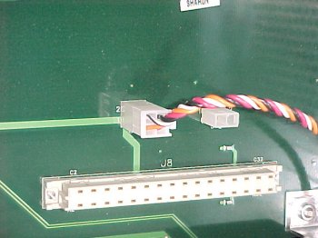
- Disconnect cable J2 from the E-box:

- Remove one of the slot blocks from the PC unit.
- Replace the disk's power cable with the new cable supplied (p/n 504L4E402):

Note:
The order of the connections is not important. However, after connecting
the connections, one connection will remain unconnected. Route this
connection along the power cable.
- Push the hard disk tray back into place. Make sure you do not short
circuit the wires.
- Reconnect cable J6 to the E-box.
- Insert the new SBC 786 board with the COM brackets and the SBC 786
connector outputs (p/n 503B1C150S):

- Affix the supplied adhesive (p/n 382-00834A), describing
the E-box cable layout, to the cover of the E-box:

- Connect the USB to the SBC. Make sure the black wire faces outwards:

- Connect the Com Adaptor cable (p/n 504L4E401) to Com 1 and J2
(E-box 50 pin) - removed in Step 6.

- Connect Com 1 to Com 2 of the SBC 786 board.
- Connect Com 2 to Com 3 of the SBC 786 board.
- Connect one end of the keyboard/mouse extension cable to the SBC 786
board, and connect the other end of the cable to the keyboard/mouse
Y splitter cable (p/n 609-00281):

- The Y splitter cable (p/n 609-00281) has two connectors: One is marked
mouse and the other keyboard. Connect the mouse connector
to the mouse and the keyboard connector to the keyboard:

- Connect the dongle adaptor and the other relevant dongles. Mount them
with bands to the left wall of the E-box:

Tip: To ensure that
the device's flat cables are connected properly, make sure the red
edge of the cable faces towards the power lead.
- If an MCU is installed, the RS-232 (p/n 504L3E325) connection
should be connected to Com 4.
After completing the installation procedure, the configuration should
resemble the following schematic:
Note:
Return the following to stock:
- MCU cable
- NUC board
- CPU board
|

