

Home | Contact Us | Submit Troubleshooting Info | Search | Help
Output | Software Solutions | Proofing | Color, Screening and Calibration | Scanning | Digital Photography | Consumables | POS
Home | Contact Us | Submit Troubleshooting Info | Search | Help
Output | Software Solutions | Proofing | Color, Screening and Calibration | Scanning | Digital Photography | Consumables | POS
Proofing Media is more fragile than plates. Loaded directly on the drum, Proofing Media is trapped in the vacuum notches and the grippers. To prevent this, the Lotem Spectrum does not expose Proofing Media directly on the drum. Instead, a Carrier is loaded first and wrapped around the drum, providing a buffer against the harsh conditions. When switching from plate making to proof making, or vice versa, a Carrier must be loaded or unloaded from the drum.
The Carrier is loaded from the upper tray of the Dual Loading Cassette (DLC).
Like the plate loading sequence, the Carrier loading sequence contains three stages. Two of the three loading stages are specific to the Carrier:
To access the relevant parameters: Hardware Tree>Loading System>Load Blanket.
In this stage, the XY Loading Bar picks up the Carrier from the upper tray and moves it to the Punch Entry.
In this stage, the XY Loading Bar takes the Carrier from Punch Entry to Drum Entry. Note that the Carrier is already punched. Therefore, it is not centered to the short pins and is not punched.
In this stage, the XY Loading Bar takes the Carrier from Drum Entry
into the Load Grippers.
This is the only stage in which Carrier loading is identical to plate loading.
The parameters used for 300µ plates in this stage, including X In Drum,
X In Drum Final, and so on, are the same as those used for Carrier loading.
Because this stage for Carrier and plate loading is identical, after every adjustment
of the parameters for plates, check to see if the new parameters work for Carriers,
and vice versa.
If an attachment problem occurs, it is recommended to change the parameters
in one of the two earlier stages. The best solution is to change the X Motor
Pos To Catch Blanket parameter. Increase this value to increase the area
of the Carrier that enters the Load Grippers, or decrease it to decrease
the area of the Carrier that enters the Load Grippers.
Note: Changing this parameter may require changing the X Motor Pos Back
After Second Centering parameter (default is 355) as mentioned in
Step 2: Load From Punch Entry To Drum Entry stage.
If you change parameter in this third stage, be sure to test them on a trial
plate when you switch to working with plates.
The Carrier unloading sequence is identical to the plate unloading sequence.
Proofing Media is loaded from the proofing tray, which is placed on the upper tray of the DLC.
The loading sequence for Proofing Media, (Receivers and Donors), is similar to the loading sequence for plates and Carriers, but has only two stages:
The Loading From Punch Entry To Drum Entry stage is not necessary, because
the media is not centered or punched.
The Receiver and Donor have different parameters, which are located in the same
table.
(Hardware Tree>Loading System>Load Proof)
In this stage, the XY Loading Bar picks up the media from the Proofing Tray and moves it to the Proof Loading Bar.
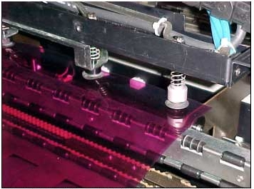
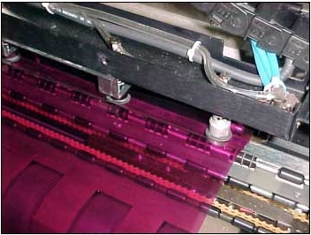
In this stage, the Proof Loading Bar attaches the Proofing Media to the drum.
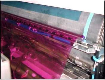
Figure 3: Drum Motor Position Ready for Donor
The unloading sequence of the Proofing Media is different from the unloading
sequence of the Carrier or the plate, and has its own registry parameters.
(Hardware>Loading System>Unload Proof)
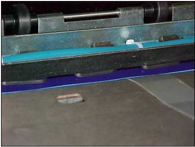
Figure 4: Unload Suction Cups at the Edge of the Donor