Home | Contact Us | Submit Troubleshooting Info | Search | Help
Output | Software Solutions | Proofing | Color, Screening and Calibration | Scanning | Digital Photography | Consumables | POS
Home | Contact Us | Submit Troubleshooting Info | Search | Help
Output | Software Solutions | Proofing | Color, Screening and Calibration | Scanning | Digital Photography | Consumables | POS
This Procedure describes how to install and adjust the Plate Detector (or Anti-Collision
Detector).The Plate Detector prevents collisions between the Carriage Head and
the plate. Collision can occur when a plate whose thickness does not match the
set thickness value is mounted on the drum, or when the plate was not properly
attached to the drum.
Prior to the installation
- For ThermoFlex 4045, you must replace the Light Detector Cover to prevent it from colliding with the Plate Detector
To replace the nozzle:
Note: The right door provides access to the L-Box.
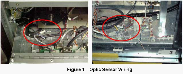
To Connect the Optic Fibers
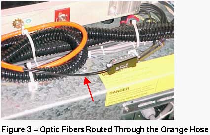
- Thread the Optic Fibers, which are part of the FCO kit, through the orange hose and route them through the Fiber Optic Chain to the Carriage.
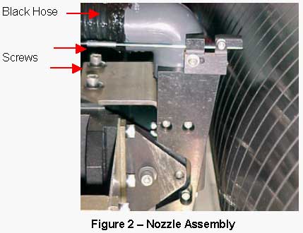
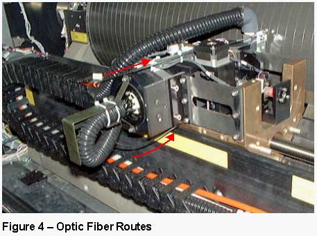
- Route the upper Optic Fiber along the black hose to the Nozzle Assembly,and the lower Optic Fiber under the Spring Leafs to the Nozzle Assembly.
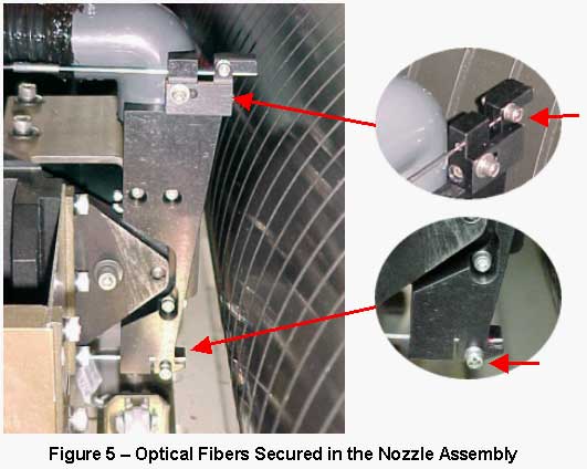
- Position the Optic Fibers as shown in Figure 5, verify that they do not protrude, and secure them by tightening the screws.
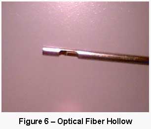
Important: Place the upper Optic Fiber with the hollow facing down, and the lower Optic Fiber with the hollow facing up (the hollows should face each other),
as shown in Figure 6.
- Turn on the main power and then turn on the Lotem.
Note: Do not install the panels.- Remove the Optic Sensor Cover.
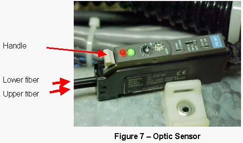
- Push down the Handle. (See Figure 7.)
- Insert the ends of the Optic Fibers into the Optic Sensor. The lower LED in the Nozzle Assembly is on.
If the upper LED is on, switch the Optic Fibers.- Push up the Handle to lock the Optic Fibers in place.
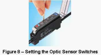
To set the Optic Sensor Switches:
Table 1 - Optic Sensor Switch Settings
Note:If the adjustment is not correct, the Red LED in the Optic Sensor may be on constantly.
- Hold a 7/64" Allen key between the transmitter and the receiver. The red LED in the Optic Sensor is on. When you remove the Allen key, the red LED is off.
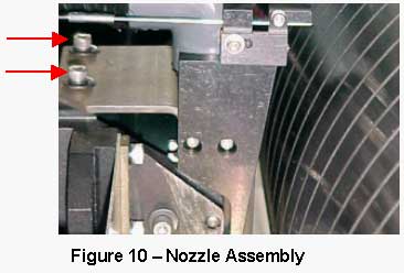
- Adjust the Nozzle position (See Appendix A).
- Manually turn the drum and check that the red LED is not on. The LED should not be on even when the plate is in front of the carriage. If the red LED is on, reduce the sensitivity of the Optic Sensor using the screwdriver.
- Place five pieces of masking tape one on top of another to form one thick piece of tape and tape it horizontally over the top or bottom edge of the plate.
- Manually turn the drum and check whether the red LED in the Optic Sensor is on when the tape passes between the transmitter and the receiver, which means that the Optic Sensor detects the excess thickness.
- Remove the thick piece of tape, manually turn the drum and check whether the red LED is on.
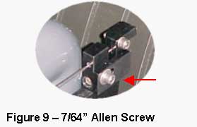
- If the red LED is on, open the 7/64" Allen screw, and move the upper Nozzle Assembly forward until the red LED is off.
- Tighten the 7/64" Allen screw. (See Figure 8.)
- When the adjustment is completed, return the Optic Sensor cover to protect the Sensor.
- Secure the black cover (above the L-Box) with the four screws you removed earlier.
- Close the Loading/Unloading tray.
- Turn on the main power to the machine, and then turn on the machine.
- Start up the Lotem application.
- Close the doors of the machine.
Description
The following procedure describes how to adjust the Nozzle position so that
the Nozzle is 0.5 mm from the plate.
To adjust the Nozzle position: