Procedure
|
|
This procedure
contains the following steps:
Checking focus
motor movement:
- Open the front door and insert a motor interlock cheater.
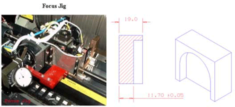
- Remove the loading tray and install the focus jig.
- In ThermoFlex Controller, send the focus motor to HP.
- On the micrometer jig, set the dial to zero.
- In ThermoFlex Controller, send the focus motor to 2500 and
check if the focus motor moves in one continuous motion.
Checking the preload
- In ThermoFlex Controller, send the focus motor to HP.
- On the micrometer jig, set the dial to zero.
- Disconnect the power plug from the focus motor.
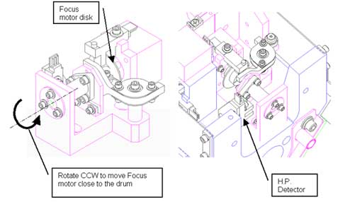
- Rotate the focus motor disk clockwise so that the optic tube moves
away from the drum until the gauge movement stops. The distance between
the focus motor HP and the point at which the gauge movement stopped
is called the Preload.
Adjusting the optic tube
- In ThermoFlex Controller, move the focus motor to 250
±30.
- Release the two screws that hold the optic tube.
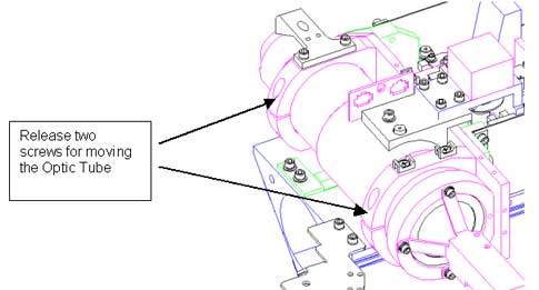
- Place the lens to drum (tombstone) jig between the optic tube and
the drum. Bring the optic tube closer to the jig and tighten the two
screws.
- Remove the lens to drum (tombstone) jig.
- Loosen the holding screw on the mechanical stopper and move the stopper
to the drum position.
- Change the Max Pos App Value parameter value to 3000.
- In ThermoFlex Controller, send the focus motor to 2800 and
check if the motor moves at least 2700 microns. Increase or decrease
the Max Pos App Value parameter value if required.
- Using the focus jig, check if the motor moves at least 2700 ±20
microns .
- If the motor did not move 2700 ±20 microns—increase
or decrease the value to which you sent the focus motor and try again,
and repeat this step until the motor moves 2700 ±20 microns.
- When the motor moves 2700 ±20—verify
that the two brackets shown following do not collide. If they collide,
the focus motor may stop moving. Reduce the focus motor Pos
parameter value to less than 2700, until the two brackets do not collide
when the motor moves. Update the Max Pos App Value parameter
value.
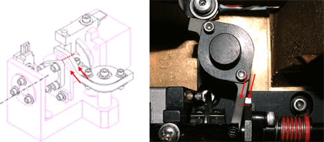
Note: If the customer does not need high values such as 2700,
find the maximum focus APP value by trial and error, until the brackets
do not collide.
- When the motor moves 2700 ±20 microns and the two parts do
not collide, tighten the two screws of the mechanical stopper at this
position.
- Change the Max Pos App Value parameter value to the value that
produced the maximum focus position without collision.
- From ThermoFlex Controller, send the focus motor to HP.
Adjusting the preload
- In ThermoFlex Controller, send the focus motor to HP.
- Remove the 3/32" hex screw that holds the focus coarse HP detector,
and move the detector according to the preload value:
- Preload value > 400 microns—towards carriage EP
- Preload value < 200 microns—towards carriage HP
- Insert and tighten the hex screw that you removed in step 2.
- Reconnect the power plug to the focus motor and send the motor to
HP.
Note: Make sure that there is preload of 200-400 microns on the
focus assembly leaf spring.
- If preload is not within 200-400 microns, repeat steps 1-4.
|