Home | Contact Us | Submit Troubleshooting Info | Search | Help
Output | Software Solutions | Proofing | Color, Screening and Calibration | Scanning | Digital Photography | Consumables | POS
Home | Contact Us | Submit Troubleshooting Info | Search | Help
Output | Software Solutions | Proofing | Color, Screening and Calibration | Scanning | Digital Photography | Consumables | POS
Product |
|
||
Background |
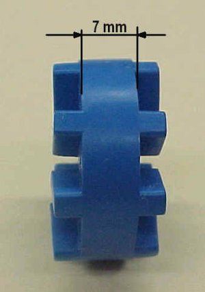
To improve screen quality the lead screw to stepper motor coupling should be adjusted for optimal flexibility. Currently the rubber damper (blue rubber damper) is being forced by a pressure of 1.5 mm, which is too great for the ThermoFlex application, and should be reduced to a pressure of 0.5 mm. |
||
Procedure |
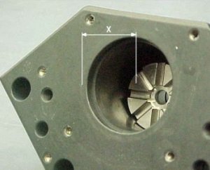
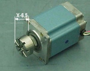
The following procedure adjusts the pressure to 0.5 mm, assuming the thickness of the rubber damper is 7 mm:
The adjusted lead screw and stepper motor coupling is shown below in Figure 3.
|
||
Technical contact(s) |
Moshe
Arviv |
||
Date submitted |
16 Dec 2002 |
||