Home | Contact Us | Submit Troubleshooting Info | Search | Help


    Output | Software Solutions | Proofing | Color, Screening and Calibration | Scanning | Digital Photography | Consumables | POS


Adjusting the drum encoder index on ThermoFlex Mid and Narrow


Product

 
  • ThermoFlex® Mid
  • ThermoFlex Narrow

Background


This procedure describes how to adjust the drum encoder index to help obtain the maximum image area around the drum.

Notes:

  • Two people are required to perform this procedure.
  • The procedure can affect the start image location (around the drum).

Requirements

  Index jig (part number 292B2M091)

Procedure


Before you begin, in Controller, in the Loading System dialog box, select Drum Init.
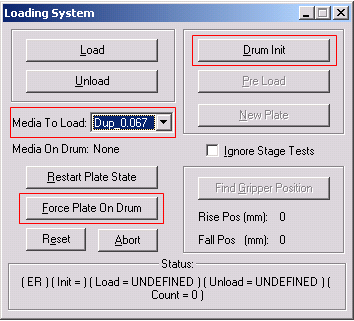
  1. Send the balance weight to the location of the largest plate size:
    1. In the Media Definition dialog box, select the maximum media size.
    2. In the Loading System dialog box, select the media that matches the size you selected in step 1a, and select Force Plate on Drum.
    3. Select Drum Init. The balance weight moves accordingly and the drum will be more stable in any position.
  2. Open the relevant doors of the platesetter to enable access to the V-groove and to the left side panel.
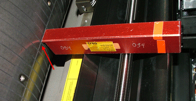
  3. Place the index jig across the V-groove, as shown, and manually rotate the drum so that the scribe line touches the index jig.
    Note: One person is required to hold the jig and drum steady while the other person adjusts the encoder.
  4. On the left side of the platesetter, open the left side panel.
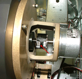
  5. On the coupling between the drum and the encoder, loosen the screw that is closer to the drum.
  6. Rotate the coupling until the reading in the Drum Motor dialog box is -15.
  7. Tighten the coupling screw and check that the reading in the Drum Motor dialog box remains -15.

Technical contact(s)
 

Content owner: Viki Arviv
See the Escalation page for escalation contacts.

Date submitted
 

14 Aug 2005


    Copyright © 2005 Creo Inc. All rights reserved. Confidential. Back to top.