Home | Contact Us | Submit Troubleshooting Info | Search | Help
Output | Software Solutions | Proofing | Color, Screening and Calibration | Scanning | Digital Photography | Consumables | POS
Home | Contact Us | Submit Troubleshooting Info | Search | Help
Output | Software Solutions | Proofing | Color, Screening and Calibration | Scanning | Digital Photography | Consumables | POS
|
|
||||||||||||||||||
Product |
|
|||||||||||||||||
|
|
||||||||||||||||||
Background |
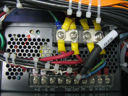
When properly adjusted, the three power supplies located in the L-box help ensure the smooth functioning of the following boards:
|
|||||||||||||||||
|
|
||||||||||||||||||
Requirements |
Digital volt meter (DVM) | |||||||||||||||||
|
|
||||||||||||||||||
Procedure |
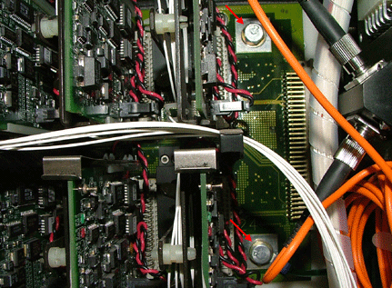
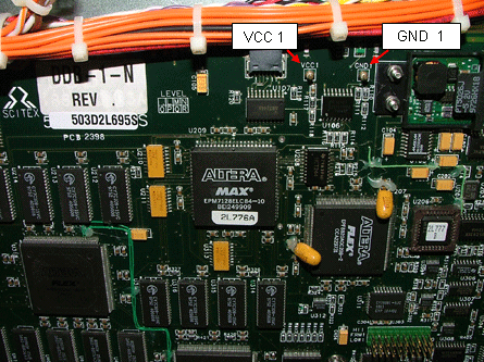
**Important: For safety reasons, the -5-V power supply does not work when any door is open. To check the -5-V power supply, attach the probes at the location shown above, route the probe wires outside of the L-box, and close all doors. Then connect the ends of the probe wires to the DVM. |
|||||||||||||||||
Technical contact(s) |
Content owner: Viki Arviv |
|||||||||||||||||
Date submitted |
21 Aug 2005 |
|||||||||||||||||