Procedure |
|
Replacing
the light detector
- In ThermoFlex Controller, click Maintenance to send
the carriage to middle position and to open the platesetter door.
- Open the unload tray.
Note: On some of the older models, you must remove the four screws
that secure the unload tray and remove the unload tray.
- Close the ThermoFlex Controller application, turn off the device,
and disconnect the power supply from the wall socket.
- Disconnect the LDT cable from the light detector.
- Three hex screws secure the light detector to the flange on the mainframe.
Important: Before you remove these three screws, mark the location
of each screw. When you reassemble the light detector, you must return
each screw to its same location to prevent damage to the nozzle during
calibration.
After you have marked the screws, remove them.
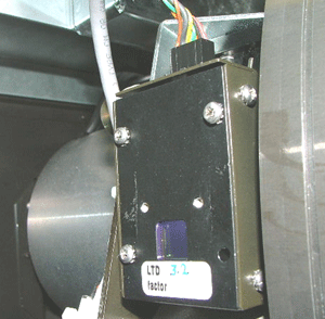
- Before installing the new light detector:
- Make sure that the new light detector has a “Danger” label.
- Write down the LD factor. You will need to record it in the
registry.
Note: If the LD factor is more than 6.06, do not install the
light detector.
- Secure the new light detector to the flange on the mainframe with
the three hex screws that you removed in step 6.
- Connect the LDT cable to the light detector.
- Close the unload tray (or reinstall it).
- Connect the power supply, turn on the device, and start ThermoFlex
Controller.
- Close all panels and doors.
Checking and adjusting light detector parameter values
- In the hardware tree, select ...IO OBJECTS > LOCAL 3 >
LDT > Light Detector and verify that the High and
Low Dac Factor parameter values match the light detector LD
factor that you wrote down in step 7.
- In the Laser Group dialog box, verify that the laser calibration value
is 600 mW (or 610 mW, as required).
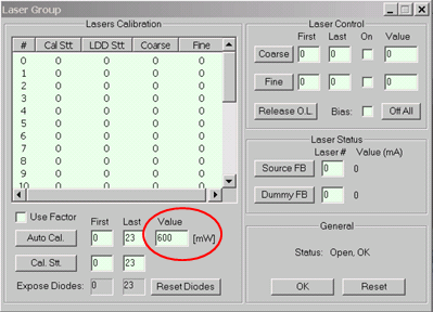
- Verify that the coarse factor is 120 ±30 and that the
laser log is 950 ±150.
- If the coarse factor is not within this range, replace the light detector.
|

