Background |
|
You can load four plates at the same time
on the ThermoFlex Narrow Magnetic Drum platesetter. However, the positions
of the registration pin holes are not always exact, relative to each other.
To overcome this problem, you can set coordinates in the workflow application
to overcome the discrepancies.
Registration on the ThermoFlex Narrow Magnetic Drum is image to punch.
This procedure describes how to set the XY mark coordinates that determine
the separation start area for up to four plates. |
Procedure |
|
Before you start, confirm that the width
and height start image areas are correctly configured.
Note: The coarse measurements in these procedures can be taken
with a ruler.
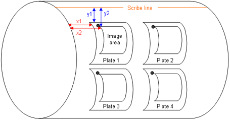
Finding the coordinates for plate A
- Load a plate.
- On the X axis, measure the following:
- Edge of drum to edge of plate (x1)
- Edge of plate to edge of punch hole (x2)
- On the Y axis, measure the following:
- Scribe line to leading edge of plate (y1)
- Edge of plate to edge of punch hole (y2)
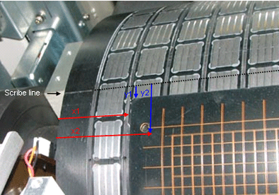
- Create a layout:
- In Brisque, in Preview environment, select File>New Imposition.
- In the Layout Setup dialog box, in the Preset Sizes
area, select Custom.
- In the Sheet Size (maximum image allowed) area,
in both of the boxes, type a value that is lower than the size of
plate A and click OK.
- In the Inventory palette, select the Marks tab,
click the arrow to the right of this tab, and select Add.
- In the Plates Marks dialog box, type the mark coordinates, as follows,
and click OK.
- X coordinate = the sum of the two measurements that you obtained
in step 2 plus the offset of the press format.
- Y coordinate = the sum of the two measurements that you obtained
in step 3 plus the offset of the press format.
- Select File>Save As, and save the layout in the required
folder location. The layout is created in the imposition job.
- In Brisque, build a grid:
- Select Service>Create a File.
- In the Create a File dialog box, set the following parameters:
| Size |
10 mm |
| Line thickness |
0.1 mm |
| File height |
200 |
| File width |
250 |
| File H res |
100 dpm |
| File W res |
100 dpm |
- Click Run.
- Create a template:
- In the Brisque environment, select View>Workflow Palette.
- In the Workflow dialog box, double-click the Arrange
folder.
- In the Arrange Parameter dialog box, in the Arrange
list, select Predefined Layout.
- In the Select a Layout box, select the layout that
you created in step 4, and click the Choose button.
- In the blank area next to the Arrange icon, right-click and select
the Plate Expose icon (or Flexo
icon for version 5.1).
- In the Plate Expose dialog box, click the Plate Expose/Flexo
icon, and set all the required parameter values.
- In the Plate Exp Parameters dialog box, select the Layout
tab.
- In the Rotate List, select Rotate 90.
- Click Save as and save the template.
- Expose the grid file using the template that you created in step 6.
- In Brisque, select View>Workflow Palette.
- In Workflow, open the template that you created in step 6.
- Select File>New File Browser and select the
grid that you created in step 5.
- Drag and drop the grid to the template and click Submit.
Note: If the results are not satisfactory, it indicates that the
width/height image start area is not properly calibrated.
Finding the coordinates for plate B
- Load the same plate at the plate B position.
- In Brisque, create a new layout for plate B as you did for the plate
A in step 4 above.
- Around the drum—plate A coordinate + 300 microns
- Along the drum—plate A coordinate + the distance
between the two pin registration holes on the drum + 300 microns
Note: Adding 300 microns ensures that the two lines of
the grid will not be imposed one on top of the other in the second exposure,
so that you can measure the distance between them.
- Expose the grid file with the second layout.
Adjusting the plate B coordinates
- In each corner of the plate, measure the difference between the grid
lines on the x and the y axis (eight measurements).
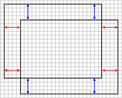
Note: Remember to take into consideration the width
of the grid lines (0.1 mm).
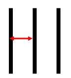
- Calculate the average of the difference between the four x axis coordinates,
and the average of the difference between the four y axis coordinates.
- In Brisque, adjust the layout for plate B:
- Around the Drum—increase or decrease the y
axis coordinate by the average difference of the four y axis coordinates
that you calculated in step 2.
- Along the Drum—increase or decrease the X
axis coordinate by the average difference of the four x axis coordinates
that you calculated in step 2.
Note: Never change the coordinates of plate 1; plate
1 is the reference.
- Expose another grid with the first layout and the adjusted second
layout, and check to confirm that the results are accurate.
Finding the coordinates for plate C
- Using a new plate, expose the grid file with the layout that you created
for plate A.
- Load the same plate at the plate C position.
- In Brisque, create a new layout for plate C as you did for plates
A and B.
- Around the drum—plate A coordinate + distance
between the two pin registration holes on the drum + 300 microns
- Along the drum—plate A coordinate + 300 microns
- Expose the grid file with the third layout.
- Adjust the plate C coordinates by following the procedure for adjusting
the plate B coordinates.
Finding the coordinates for plate D
To find the plate D coordinates, follow the procedure for finding the
plate C coordinates, with the following differences:
- Around the drum—plate A coordinate + the distance
between the two pin registration holes on the drum + 300 microns
- Along the drum—plate A coordinate + the distance
between the two pin registration holes on the drum + 300 microns
Checking the final coordinates
- On a new plate, create a grid with all four layouts, but do not add
the 300 microns.
- Examine the results. The grid lines should be imposed upon each other.
They should be a bit thicker than 0.1 mm, but should not have more
than a 50-micron tolerance.
|

