
Home | Contact Us | Submit Troubleshooting Info | Search | Help


    Output | Software Solutions | Proofing | Color, Screening and Calibration | Scanning | Digital Photography | Consumables | POS


Thin Lines Appear in the Solid Area of the Exposed Image in ThermoFlex Mid and Narrow


Product

 
  • Kodak ThermoFlex Mid
  • ThermoFlex Narrow

Symptoms


In every swath, thin lines appear, mostly in the solid area (the area that is 100% exposed) between the first and last diodes.


Cause


During exposure, there is a time lapse between the performance of the first and last diodes. During this time the media may cool slightly. If this occurs, thin lines or may be seen on the image, in the solid area between the the first and last diodes.

Note: This is more common with 600 mW diodes, since they are not as strong as 1 W diodes.


Solution


The strength of the first and last three diodes must be increased to overcome the effect of the cooling of the media, and produce a uniform image.

The following procedure describes how to increase the strength of the first and last three diodes to create a clean solid.
  1. Create a file with a dot percent of 0 and 50.
    • Configuration without Brisque:
      Ask the customer to create a file with a dot percent of 0 and 50.
    • Configurations with Brisque:
      1. From the Brisque launch pad, select Services, and double-click Create File.
      2. Select the following parameters:
        • File type—CT
        • Strip type—HS
        • File width—20 mm (around)
        • File height—20 mm (along)
        • File H res—12 dpm
        • File W res—12 dpm
        • Num V strips—2
        • Separations—CMYK all from 100% to 50%.
  2. In the Hardware tree, browse to boards and right-click DDB card.
  3. In the DDB dialog box, in the Lasers Factor section, click the Reset All to 0 button,and then expose the file that you created in step 1 for reference.
    Note: Use the customer's screen sets for the exposure.
  4. To see differences on the plate, in Regedit, browse to
    HKEY_LOCAL_MACHINE\SOFTWARE\Scitex\Projects\LOTEMFLEXO\EXPOSE\.... and verify that the Laser Factor From Host Enable parameter is 0.
  5. In the DDB dialog box, in the Lasers Factor section, click the Apply button.
  6. Restart the application.
  7. Perform test 1: Set DDB factors of 10, 7, and 4 for the first three diodes, according to the table following, and expose the first test file.
    Diode
    DDB value added
    Test 1
    Test 2
    Test 3
    0
    10
    10
    1
    7
    7
    2
    4
    4
    21/45
    4
    4
    22/46
    7
    7
    23/47
    10
    10
  8. Perform test 2: Set the DDB factors for the last three diodes as indicated in the table, and expose the second test file.
  9. Perform test 2: Set the DDB factors for both the first and the last three diodes, as indicated in the table, and expose the third test file.
  10. Examine the media on a light table and select the exposure in which the solid area is cleanest.
  11. If the solid is not clean, increase each diode factor value by 2, and perform the test again.
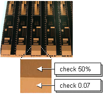
  12. After a clean solid is obtained, check the following:
    1. Select the strip for which the 50% dot area measures 50%.
    2. Measure the density in the solid area. A good density reading should be 0.07 or less.

Test


Perform the ITP (Installation Test Procedure and verify good image quality.


Technical contact(s)
 

Viki Arviv

Submitted by
 

Frederic Mayot

Date submitted
 

13 Mar 2006


    Copyright © 2005 Creo Inc. All rights reserved. Confidential. Back to top.