Procedure |
|
- From Controller, open the front door of the platesetter.
- Exit Controller and turn off the platesetter.
- Open the left side door and the left side panel.
- If the configuration includes the MCU, disconnect the MCU from the
platesetter.
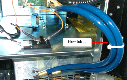
- Disconnect the flow tubes from the chiller.
- On the floor of the mainframe, open the four hex screws that secure
the chiller, and then remove the chiller.
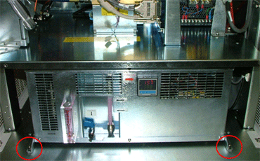
- Insert the new chiller and insert and tighten the four hex screws.
- Connect the flow tubes to the chiller.
- Fill the chiller with coolant:
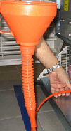
- Connect the 8 mm orange air tube to a funnel.
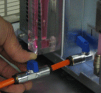
- Connect the other end of the air tube (with the connector tap)
to the drain tap.
Note: If the air tube with connector tap is not available,
use a regular 8 mm orange air tube.
- Open the drain tap and the connector tap.
- Fill the chiller with coolant until the coolant reaches the top
level.
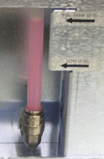
- Close the drain tap and the connector tap, and then disconnect
the air tube.
Note: To disconnect the air tube, pinch the clips on the connector.
- If the chiller has been in an upright position for 3 hours, connect
the chiller to the LDA head.
Important: If the chiller has not
been upright for the past 3 hours, or if you are not sure, wait 3 hours
before you connect the chiller to the LDA head, until the oil in the
chiller compressor has settled.
- Wipe up any coolant from the CPC ports, the flow tubes, and anywhere
else that it may have spilled.
Important: This step is crucial
for the success of future leakage diagnostics.
- Power up the chiller, wait 1/2 hour, and then test the installation,
as described in the following Test section.
|
Test |
|
After the chiller is connected to the power for 1/2 hour, check the following:
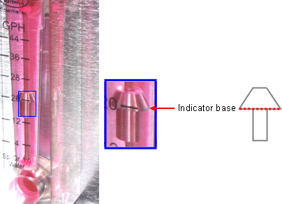
- The flow meter indicator rises, and its base reaches the following
level:
- 50 Hz chiller—above 12 GPH
- 60 Hz chiller—above 22 GPH
- Coolant level is consistant throughout the two hours
- No leaks are present
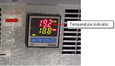
- The chiller controller temperature, indicated by the upper red
reading, is within the allowed range: 18.8° C – 20.2° C.
|

