| |
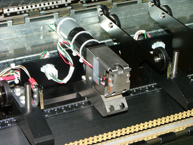
This procedure includes the following sections:
Removing the Spoiler
- Verify that the front and side doors of the platesetter are open and
that the platesetter is shut down and disconnected from the main power
supply.
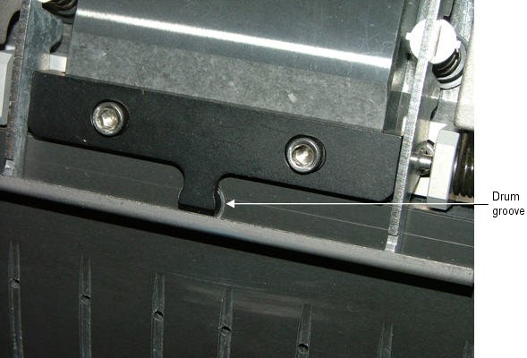
- If there is center punch groove on the drum, go to Installing
the Central Punch Pin.
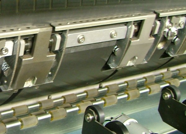
- At the front of the platesetter (loading direction), from the middle
spoiler on the drum, remove the two hex screws, and then remove the
spolier.
|
|
|
|
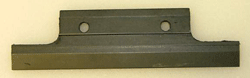
Fix spoiler
|
Spring spoiler
|
- Install the drum drilling jig in place of the spoiler that you removed
in step 3.
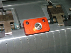
- Before drilling, place a piece of protective cloth or paper over the
drum area to prevent slugs and debris from getting into the platesetter.
- Insert the 12-mm drum drilling tool from the kit into the drill, and
then drill to a depth of 1 mm.
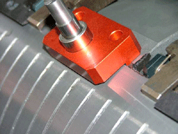
- Remove the drill and the jig from the drum.
Installing the Central Punch Pin
- At the rear of the platesetter, uninstall the unloading assembly by
removing the two screws that secure it, and disconnect any relevant
connections.
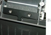
- Install the new spoiler on the drum.
|
|
|
|
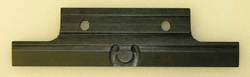
Center pin for fix spoiler
|
Center pin for spring spoiler
|
- Verify that there is a spare locking nut in the center of the punch
bar.
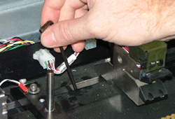
- If there is not a spare locking nut, mark the location of each of
the existing punches.
- One by one, remove the two punches on the left side of the middle
punch, and then remove the middle punch.
- Thread the locking nut into the groove to the location in the middle
of the punch bar where the new punch will be installed.
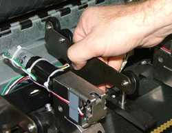
- Install the punch and tighten the hex screw into the locking nut.
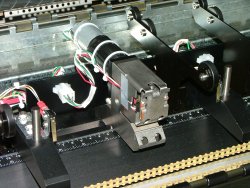
- Connect the punch connector to the punch 3 Molex™ connector.
- Reinstall the unloading assembly.
Defining the Central Punch in the Registry
- In the Kodak Controller software, locate IO OBJECTS\Loader\Detectors\Punch
Motor#3 Home Pos. Detector and change the Open parameter
value from 0 to 1.
- Locate IO OBJECTS\Loader\Detectors\Punch Motor#3 and change
the Open parameter value from 0 to 1.
- Locate IO OBJECTS\Punch System and change the Open parameter
value from 0 to 1.
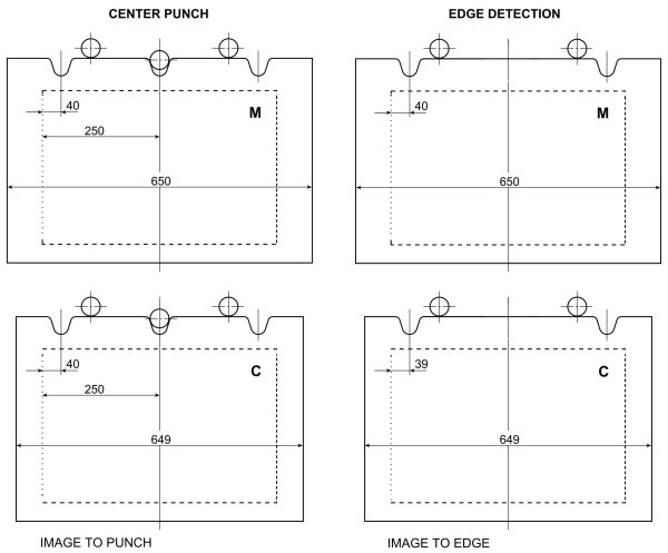
- Define the center punch as a spiral punch unit by locating
IO OBJECTS\Punch System\Punch System and changing the Punch
Spiral unit parameter value from none to Punch Motor #03.
Note: This ensures that this punch punches every plate, even
if there is no punch selected.
Disabling the Edge Detection System
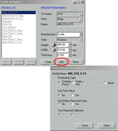
- In the Controller software, select Settings > Media Definition.
- In the Media Definition dialog box, in the Media List area,
select the relevant customer media (in Engineer mode), and then click
Adv.
- In the Media Advanced Properties dialog box, select Centring Punch.
- If the platesetter is a Quantum platesetter:
- In either SPlot or Service Shell, disable edge detection from the
TMCE board.
- At the command prompt, type
access dev, and then type
option edgedetect disable.
Note: You must also perform centering the image on the plate
from the TMCE. Perform one of the following actions:
- At the
TH2>> prompt, type set h1c
sssa (the value is in mil = 1/1000 inch), and press enter.
- At the
Quantum>> prompt, type set
hdp sssa (the value is in mil = 1/1000 inch), and press
enter.
- If the platesetter is a fiber head platesetter,in the registry, locate
either Lotem400\EXPOSE or Magnus400\EXPOSE and change
the Plate Edge Detection Enable parameter value from 1 to 0.
Adjusting the Image to Punch Position
- If the platesetter is either a Lotem 400 FH or Lotem 400 Quantum platesetter,
in the registry, locate Lotem400\MACHINE\ and adjust the Height
Start Image Area (mm) parameter value accordingly.
- If the platesetter is a Magnus 400 platesetter with software earlier
than version 3.91, in the registry, locate Magnus400\MACHINE\
and adjust the Height Start Image Area (mm) parameter value accordingly.
- If the platesetter is a Magnus 400 platesetter with version 3.91 software
and later, in the registry, locate Magnus400\MACHINE\ and adjust
the Drum Edge Position parameter value accordingly.
|