Procedure |
|
Important: Only experienced engineers should perform the following
procedure.
Note: During the procedure, apply a drop of Loctite®
adhesive on all the screws for which you are securing parts.
- Perform a preload sequence.
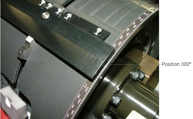
- Position the tail gripper assembly so that the middle of the assembly
is at 300° by activating the tail gripper and moving the drum.
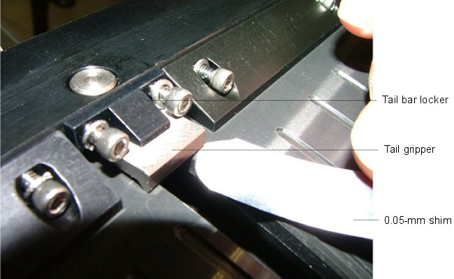
- Verify that the four tail bar lockers are pressed down as far as possible
and that a 0.05-mm shim cannot be easily inserted under the tail gripper.
- If you can easily insert the shim under the tail gripper, adjust the
clearance.
- Loosen the two tail gripper screws.
- Press down on the tail bar locker, pushing it down as far as possible.
- When the tail bar locker is pressed down as far as possible, tighten
the two screws.
- Verify that the clearance between the seven tail gripper spoilers
and the drum is 0.05 mm.
- Insert the 0.05-mm shim under the first tail gripper spoiler and
slide it from one side of the tail gripper spoiler to the other
side. You should be able to slide the shim, but with some resistance.
- If the shim slides easily from one side to the other, adjust the
clearance.
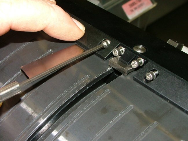
- Loosen the screws that secure the tail gripper spoiler to the
tail gripper assembly.
-
Next to the right tail gripper spoiler screw, press down on the
front of the tail gripper spoiler and tighten the tail gripper
spoiler screw. Adjust the left tail gripper spoiler screw in the
same way.
Note: If there is not enough clearance, loosen the screw,
press on the back of the tail gripper spoiler, and then tighten
the screw.
- Repeat steps 4a4d for each of the remaining six tail gripper
spoilers.
|