Procedure |
|
Before you begin:
- On the platesetter, if applicable, remove the cheater to disconnect
the motor interlock.
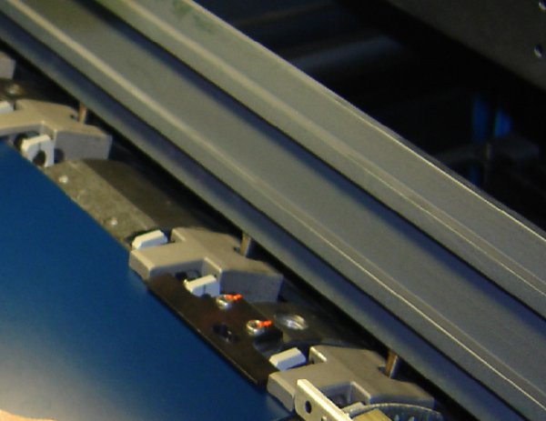
- Manually drag the tail gripper to the end of the drum track until
it is parallel to the head gripper (preload position).
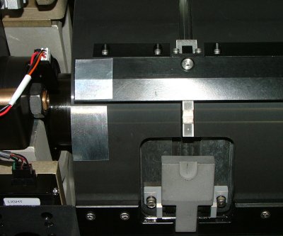
- Insert the cheater to reconnect the motor interlock.
This procedure includes instructions for:
Attention: To calibrate grippers, the drum index must be correctly
adjusted.
Before you can configure the grippers, you must verify that you are working
in Service Engineer mode.
- In the Magnus or Lotem Controller software,
on the Operations toolbar, select Utilities > Users.
- In the Define User window, in the User Type list, select Service
Engineer.
- In the Password box, type the appropriate password and click
OK.
Note: The password is case-sensitive.
- On the Operations toolbar, select Utilities > Hardware.
- In the Hardware window, expand the Loading System branch and
double-click the Loading System node.
- In the Loading System Dialog window, under Initializing, click Drum.
- In the Hardware window, open the following windows:
- Drum Motor—expand Drum System and double-click Drum
Motor.
- Left Load Gripper End Pos. Detector—expand Drum System
> Gripper System > Load Gripper and double-click
Left Load Gripper End Pos. Detector.
- Left Load Gripper Home Pos. Detector—expand Drum System
> Gripper System > Load Gripper and double-click
Left Load Gripper Home Pos. Detector.
- Load Gripper enable Detector—expand Drum System > Gripper
System > Load Gripper and double-click Load Gripper
Enable Detector.
- Load Gripper Valve—expand Drum System > Gripper System
> Load Gripper and double-click Load Gripper Valve.
- Right Load Gripper End Pos. Detector—expand Drum System
> Gripper System > Load Gripper and double-click
Right Load Gripper End Pos. Detector.
- Right Load Gripper Home Post. Detector—expand Drum System
> Gripper System > Load Gripper and double-click
Right Load Gripper Home Pos. Detector.
- To verify that the Load Gripper Enable detector is working properly:
- In the Drum Motor window, on the Operation tab, select
Position and:
- For a Magnus platesetter, type
–218
- For a Lotem platesetter, type
–207
- In the By speed box next to Position, type
100.
- Click Start.
- In the Load Gripper Enable Detector window, verify that the Load
Gripper Enable detector is ON.
- To verify that the left and right load-gripper end-position detectors
and the left and right load-gripper home-position detectors are working
properly:`
- In the Load Gripper Valve window, on the Operation tab,
click Start.
- Verify that the left and right load-gripper end-position detectors
and the left and right load-gripper home-position detectors change
from ON to OFF.
- In the Load Gripper Valve window, click Stop.
- On the platesetter, to visually verify that the gripper actuator operates
smoothly:
- In the Load Gripper Valve window, on the Operation tab,
click Start.
- During drum entry and exit, verify that the gripper actuator's
piston air valves operate smoothly.
- Verify that the left and right, end- and home-position detectors
change simultaneously from OFF to ON when the gripper actuator presses
on the head grippers.
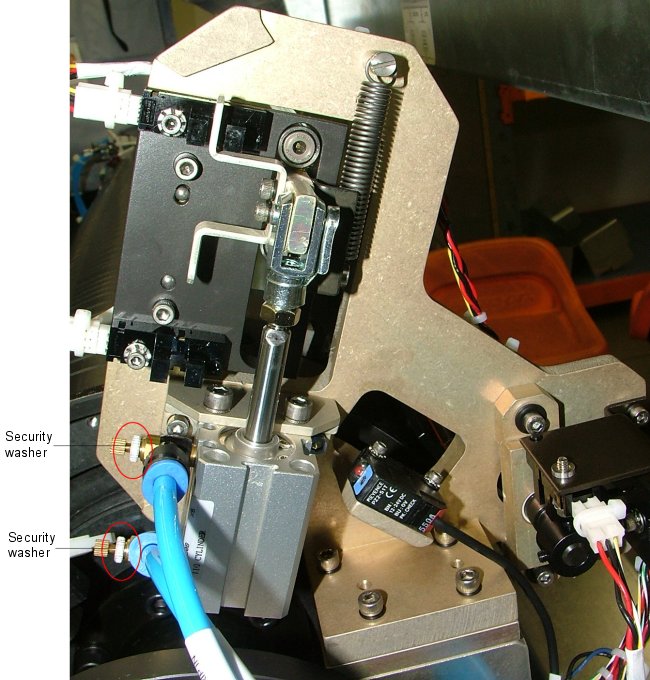
If they are not synchronized, adjust the gripper actuator piston
air valves.
- In the Load Gripper Valve window, on the Operation tab,
click Stop.
- Update the registry with the correct open and close gripper-actuator
position:
- In the Load Gripper Valve window, on the Operation tab,
click Start and:
- For a Magnus platesetter, the gripper actuator activates at
position –218.
- For a Lotem platesetter, the gripper actuator activates at
position –207.
- Remove the interlock cheater to manually rotate the drum.
- When the load gripper turns on and the gripper actuator presses
on the grippers, manually rotate the drum forward until the gripper
actuator touches the edge of the head gripper's slotted groove.
- In the Drum Motor window, on the Operation tab, find the
current drum motor position and write it down.
- In the registry, go to Loading System\Loading System Setup\Load
Head Gripper Location (mm) and type the value that is 2 mm
less than the drum position that you wrote down in the previous
step.
- In the Load Gripper Valve window, on the Operation tab,
click Stop.
- On the gripper actuator, close the security washers on the piston
air valves.
- In the Hardware window, open the following windows:
- Drum Motor—expand Drum System and double-click Drum
Motor.
- Left Unload Gripper End Pos. Detector—expand Drum System
> Gripper System > Unload Gripper and double-click Left
Unload Gripper End Pos. Detector.
- Left Load Gripper Home Pos. Detector—expand Drum System
> Gripper System > Unload Gripper and double-click
Left Unload Gripper Home Pos. Detector.
- Load Gripper enable Detector—expand Drum System > Gripper
System > Unload Gripper and double-click Unload
Gripper Enable Detector.
- Load Gripper Valve—expand Drum System > Gripper System
> Unload Gripper and double-click Unload Gripper Valve.
- Right Load Gripper End Pos. Detector—expand Drum System
> Gripper System > Unload Gripper and double-click
Right Unload Gripper End Pos. Detector.
- Right Load Gripper Home Post. Detector—expand Drum System
> Gripper System > Unload Gripper and double-click
Right Unload Gripper Home Pos. Detector.
- To verify that the Unload Gripper Enable detector is working properly:
- In the Drum Motor window, on the Operation tab, select
Position and:
- For a Magnus platesetter, type
–584
- For a Lotem platesetter, type
–551
- In the By speed box next to Position, type
100.
- Click Start.
- In the Unload Gripper Enable Detector window, verify that the
Unload Gripper Enable detector is ON.
- To verify that the left and right unload-gripper end-position detectors
and the left and right unload-gripper home-position detectors are working
properly:
- In the Unload Gripper Valve window, on the Operation tab,
click Start.
- Verify that the left and right unload-gripper end-position detectors
and the left and right unload-gripper home-position detectors change
from ON to OFF.
- In the Unload Gripper Valve window, on the Operation tab,
click Stop.
- On the platesetter, to visually verify that the gripper actuator operates
smoothly:
- In the Unload Gripper Valve window, on the Operation tab,
click Start.
- During drum entry and exit, verify that the gripper actuator's
piston air valves operate smoothly.
- Verify that the left and right, end- and home-position detectors
change simultaneously from OFF to ON when the gripper actuator presses
on the head grippers.
If they are not synchronized, adjust the gripper actuator piston
air valves.
- In the Unload Gripper Valve window, on the Operation tab,
click Stop.
- Update the registry with the correct open and close gripper-actuator
position:
- In the Unload Gripper Valve window, on the Operation tab,
click Start and:
- For a Magnus platesetter, the gripper actuator activates at
position –584.
- For a Lotem platesetter, the gripper actuator activates at
position –551.
- In the Drum Motor window, turn off the drum motor.
- When the load gripper turns on and the gripper actuator presses
on the grippers, manually rotate the drum forward until the gripper
actuator touches the edge of the head gripper's slotted groove.
- In the Drum Motor window, on the Operation tab, find the
current drum motor position and write it down.
- In the registry, go to Machine\Unload Head Gripper Location
(mm) and type the value that is 2 mm less than the
drum position that you wrote down in the previous step.
- In the Unload Gripper Valve window, on the Operation tab,
click Stop.
- On the gripper actuator, close the security washers on the piston
air valves.
- In the Hardware window, open the following windows:
- Drum Motor—expand Drum System and double-click Drum
Motor.
- Left Unload Gripper End Pos. Detector—expand Drum System
> Gripper System > Unload Gripper and double-click Left
Unload Gripper End Pos. Detector.
- Left Load Gripper Home Pos. Detector—expand Drum System
> Gripper System > Unload Gripper and double-click
Left Unload Gripper Home Pos. Detector.
- Load Gripper enable Detector—expand Drum System > Gripper
System > Unload Gripper and double-click Load Gripper
Enable Detector.
- Load Gripper Valve—expand Drum System > Gripper System
> Unload Gripper and double-click Unload Gripper Valve.
- Right Load Gripper End Pos. Detector—expand Drum System
> Gripper System > Unload Gripper and double-click
Right Unload Gripper End Pos. Detector.
- Right Load Gripper Home Post. Detector—expand Drum System
> Gripper System > Unload Gripper and double-click
Right Unload Gripper Home Pos. Detector.
- To verify that the Unload Gripper Enable detector is working properly:
- In the Drum Motor window, on the Operation tab, select
Position and:
- For a Magnus platesetter, type
208
- For a Lotem platesetter, type
191
- In the By speed box next to Position, type
100.
- Click Start.
- In the Unload Gripper Enable Detector window, verify that the
Unload Gripper Enable Detector is ON.
- To verify that the left and right unload-gripper end-position detectors
and the left and right unload-gripper home-position detectors are working
properly:
- In the Unload Gripper Valve window, on the Operation tab,
click Start.
- Verify that the left and right unload-gripper end-position detectors
and the left and right unload-gripper home-position detectors change
from ON to OFF.
- In the Unload Gripper Valve window, on the Operation tab,
click Stop.
- On the platesetter, to visually verify that the gripper actuator operates
smoothly:
- In the Unload Gripper Valve window, on the Operation tab,
click Start.
- During drum entry and exit, verify that the gripper actuator's
piston air valves operate smoothly.
- Verify that the left and right, end- and home-position detectors
change simultaneously from OFF to ON when the gripper actuator presses
on the tail grippers.
- In the Unload Gripper Valve window, on the Operation tab,
click Stop.
- Update the registry with the correct open and close gripper-actuator
position:
- In the Unload Gripper Valve window, on the Operation tab,
click Start and:
- For a Magnus platesetter, the gripper actuator activates at
position 208.
- For a Lotem platesetter, the gripper actuator activates at
position 191.
- In the Drum Motor window, turn off the drum motor.
- When the load gripper turns on and the gripper actuator presses
on the tail grippers, manually drag the drum with the tail grippers
until it is parallel to the edge of the drum groove.
- In the Drum Motor window, on the Operation tab, find the
current drum motor position and write it down.
- In the registry, go to Loading System\Drum\Init Tail Gripper
Pos (mm) and type the value that you wrote down in the previous
step.
- In the Unload Gripper Valve window, on the Operation tab,
click Stop.
|