|
Product |
|
- Kodak® Magnus™ 400
- Kodak Magnus 400 Xpose™
|
|
Background |
|
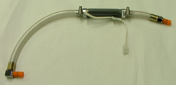
This procedure describes how to replace the flow switch.
|
|
|
|
Flow switch
|
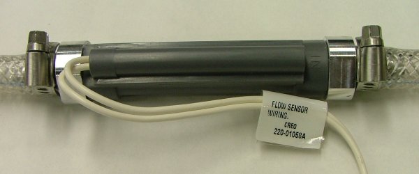
Flow switch wiring
|
|
|
Procedure |
|
- Verify that all components on the flow switch assembly are tightly
secured.
- In the Magnus Controller software, open the front door of the platesetter.
- Quit Magnus Controller and turn off the platesetter.
- Open the left-side door and the left-side panel.
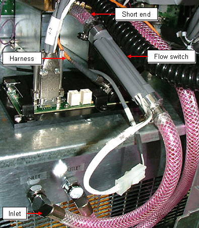
- Disconnect the harness, as shown under Images.
- Disconnect the flow switch assembly from the inlet CPC port on the
chiller and from the CPC port on the LDA head, as shown under Images.
- Connect the updated flow switch assembly as follows:
- Connect the short end of the flow switch assembly to the CPC
port on the LDA head, as shown under Images.
- Connect the long end of the flow switch assembly to the inlet
CPC port on the chiller, as shown under Images.
- Connect the two-pin minifit of the harness to the two-pin connector
on the flow switch.
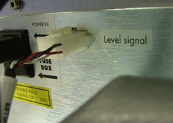
- On the right side, connect the eight-pin minifit of the level signal
harness to the eight-pin connector on the chiller.
- Turn on the platesetter and start Magnus Controller.
During this procedure, the coolant level is expected to decrease, so
you will need to refill the coolant after startup.
- Turn off the chiller.
- Refill the chiller with coolant.
- Wipe away any spilled coolant.
- Test the flow switch.
|
|
Images |
|
|
|
Test |
|
After the chiller has been operating for 30 minutes,
verify the following:
- No warning messages related to the flow switch appear.
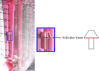
- As the flow meter indicator rises, its base reaches the following
level:
- 50 Hz chiller: above 12 GPH
- 60 Hz chiller: above 22 GPH
- The coolant level remains consistant for the two hours.
- No leaks are present.
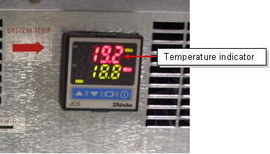
- The chiller controller temperature, indicated by the upper red
reading, is within the allowed range: 18.8° C—20.2° C.
|
|
Technical contact(s) |
|
Content owner: Mario Amir
See the Escalation page for escalation
contacts.
|
Date submitted |
|
27 Oct 2005
|