Procedure |
|
This procedure includes the following sections:
Before you can reset the Local3 board, verify that the Memtool software
is installed on the workstation.
Note: Memtool 3 might have been installed during production.
- On the Windows desktop, select Start > Programs >
Infineon Memtool 3 > Infineon - Memtool 3.
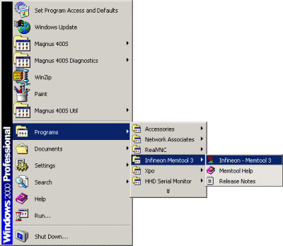
- If Memtool 3 is installed on your workstation, proceed to Starting
Memtool 3.
If Memtool 3 is not installed on your workstation, you must download
it from TechPlanet to your workstation.
- From the Downloads
page, download the infineon_memtool_3_4_0.exe, to C:\Magnus\Util\Local3
Monitor\Infineon Memtool 3 file.
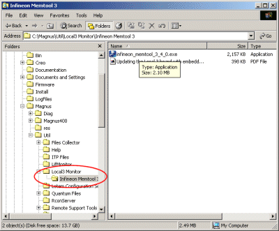
- Double-click the infineon_memtool_3_4_0.exe file.
- Follow the steps in the InstallShield Wizard to install Memtool
3 on your workstation.
- At the end of the installation, click Finish.
- On the desktop, select, Start > Programs > Infineon Memtool
3 > Infineon - Memtool 3.
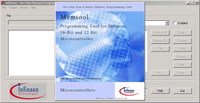
The Memtool splash screen appears, followed by the main Memtool window.
Tip: Click the Memtool splash screen to quickly display only
the main Memtool window.
-
From the Memtool menu, select Target > Change.
The Select Target dialog box appears.
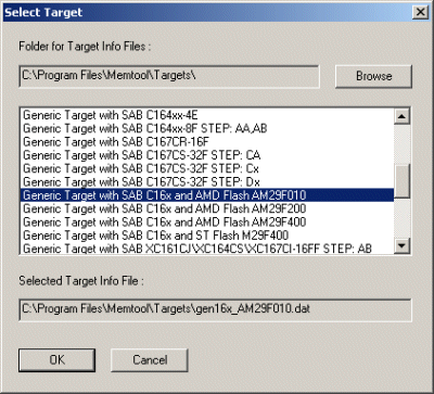
- Select the Generic Target with SAB C16x and AMD Flash AM29F010
file and click OK.
The COM port to which your platesetter is connected depends on the type
of platesetter with which you are working:
- Magnus 400 (manual): COM 1 on Local3
- Magnus 400 with MCU:
- COM 1 on Local3
- COM 2 on Loader Local3
Note: During the machine loading process, an error message
will appear if there is a communication problem with either COM
1 or COM 2.
To set the serial interface on Magnus 400 (manual):
- From the Memtool menu, select Target > Setup Communication
Port.
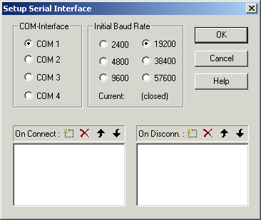
- In the Setup Serial Interface dialog box, do the following actions:
- In the COM-Interface area, verify that COM 1 is selected.
- In the Initial Baud Rate area, verify that 19200 is
selected.
- Click OK.
To set the serial interface on Magnus 400 with MCU:
- From the Memtool menu bar, select Target > Setup Communication
Port.
The Setup Serial Interface dialog box appears.
- In the Setup Serial Interface dialog box, do the following actions:
- In the COM-Interface area, if COM 2 was identified as the
faulty port (Loader Local3 board error message), select COM 2.
Otherwise, verify that COM 1 is selected.
- In the Initial Baud Rate area, verify that 19200
is selected.
- Click OK.
If you are working with a manual Magnus 400 platesetter, you need
to install the BSL jig on the motherboard that is attached to the Local3
board in the left side door.
If you are working with a Magnus 400 with MCU configuration and
a Loader Local3 error appeared during the machine loading process, you
need to install the BSL jig on the Loader Local3 board, which is located
in the lower-front panel. Otherwise, install the BSL jig on the Local3
board in the left MCU door, according to the Magnus 400 procedure.
To install the BSL jig on Magnus 400:
- On the platesetter, open the left side door.
- Release the two screws that secure the Local3 board protective cover
to the platesetter, and lift open the cover.
- Connect the BSL connector on the BSL jig to the BSL NMI
Conn connector on the motherboard.
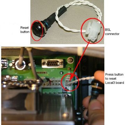
- To reset the Local3 board, press the black button that is connected
to the other end of the BSL jig.
Tip: If all the LEDs on the Local3 box light up when you press
the reset button, you have successfully reset the Local3 board.
To install the BSL jig on Magnus 400 with MCU:
- On the platesetter, open the left and right MCU doors.
- Remove the four screws that secure the lower-front panel to the platesetter
(two screws on each side of the panel), and remove the panel and set
it aside.
- Remove the Loader Local3 board.
- Connect the BSL connector on the BSL jig to the BSL NMI
Conn connector on the motherboard that is attached to the Loader
Local3 board.
- Return the Loader Local3 board.
- To reset the Loader Local3 board, press the black button that is connected
to the other end of the BSL jig.
Tip: If all the LEDs on the Loader Local3 box light up when you
press the reset button, you have successfully reset the Loader Local3
board.
- In Memtool, verify that the Enabled check box is selected and
click Connect.
A list of the Flash sectors in the selected FLASH/OTP module appears.
Note: After you click Connect, the button changes to Disconnect.
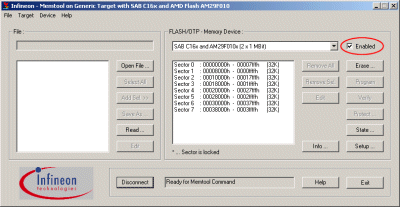
- Click Erase.
The Select FLASH Sectors for Erase dialog box appears.
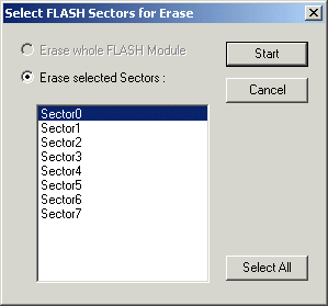
- Select Sector0 and click Start.
Memtool starts erasing Sector 0 and the Execute Memtool Command dialog
box appears.
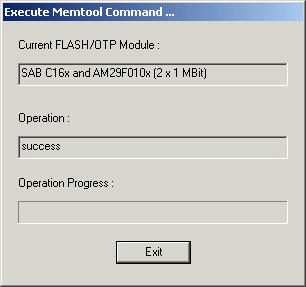
- When Memtool has successfully erased the selected sector, click Exit.
- In Memtool, click Open File and browse to C:/Magnus/Magnus400/Upload/Local3.
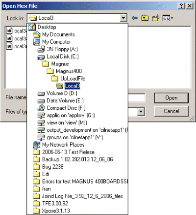
- In the Local3 folder, select the local3mon_v6.hex file
and click Open.
The contents of the selected file appear in the left pane in Memtool.
- To add the files to the selected module, click Select All,
and then click Add Set.
- Click Program.
Memtool starts loading the selected Flash files and the Execute Memtool
Command dialog box appears.
- When Memtool has successfully loaded the Flash files, click Exit.
- To close the Memtool software, click Exit.
- Shut down the workstation and turn off the platesetter.
- Turn on the platesetter and start Magnus Controller.
- Verify that no Local3 error messages appear.
- Remove the BSL jig:
- On Magnus 400 (manual), disconnect the BSL connector that
is connected to the BSL NMI Conn connector on the motherboard, and
remove the jig.
- On Magnus 400 with MCU, disconnect the BSL connector that
is connected to the BSL NMI Conn connector on the motherboard that
is attached to either the Loader Local3 board (COM 2) or the Local3
board (COM 1), and remove the jig.
- Close the platesetter doors:
- On the Magnus 400, close the Local3 board protective cover
and close the left side door.
- On the Magnus 400 with MCU, return the lower-front panel
and the four screws that secure the lower-front panel to the platesetter
(two screws on each side of the panel), and then close the left
and right MCU doors.
|

