Background |
|
Each laser diode has an outer shield, an inner shield, and an optic fiber.
You can repair a faulty diode by splicing the optic fiber from the spare
diode to the optic fiber of the faulty (original) diode.
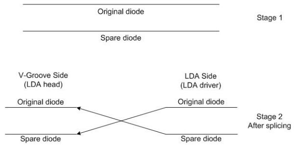
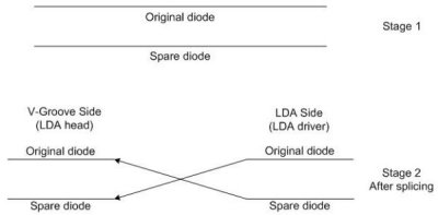
Splicing the optic fibers is performed in a crisscross pattern, as shown
in the following diagram.
|
Procedure |
|
This procedure describes how to strip, cut, and splice a single laser
diode.
Using the crisscross method, work in pairs first splicing the optic
fiber on the spare diode (connected to the LDA driver) to the optic fiber
on the original (faulty) diode (connected to the LDA head), and then splicing
the optic fiber on the original (faulty) diode (connected to the LDA driver)
to the optic fiber on the spare diode (connected to the LDA head).
Warning: You must wear an antistatic wrist band when replacing
or splicing a faulty laser diode.
This procedure includes instructions for:
Locating and cutting the laser diodes
- In the L-box, locate the faulty laser diode and identify a spare
laser diode.
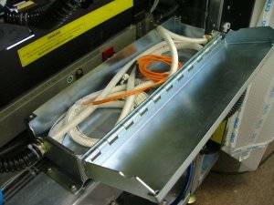
- On the diode harness inside the L-box, at the access hole, cut both
the original (faulty) diode and the spare diode.
Two laser diode ends (faulty and spare) are connected to the LDA
driver (LDA Side label) and two laser diode ends (faulty and spare)
are connected to the laser diode array (LDA) head (V-Groove Side label).
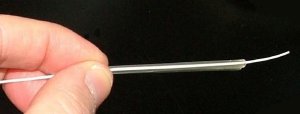
- Carefully slide a protective shrink tube over the cut end of the first
laser diode that you want to repair.
Stripping the outer fiber shield
Strip off the outer fiber shield on both ends of the cut laser diodes—the
end connected to the LDA driver and the end connected to the LDA head.
- Set the fiber stripper to 0.60 and 1.00 mm and
the stopper on the stripper to about 4 cm (1.5 in.).
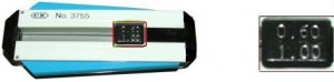
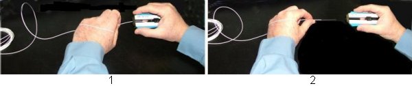
- Carefully insert about 4 cm (1.5 in.) of the cut laser diode
into the fiber stripper until it reaches the stopper.
- While firmly holding the cut end of the laser diode in one hand, squeeze
the fiber stripper together with the other hand and strip off 900 microns
from outer fiber shield to expose the inner fiber shield.

Stripping the inner fiber shield
The inner shield is very thin and should be completely removed. A successful
strip will leave 4 cm (1.5 in.) of exposed optic fiber.
Strip off the inner fiber shield on both ends of the cut laser diodes—the
end connected to the LDA driver and the end connected to the LDA head.
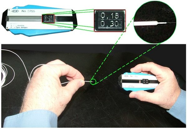
- Set the fiber stripper to 0.18 and 0.30 mm and the stopper
on the stripper to 4 cm (1.5 in.).
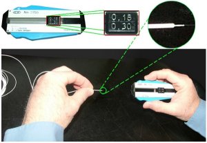
- Carefully insert about 4 cm (1.5 in.) of the exposed inner
shield into the stripper until it reaches the stopper.
- While firmly holding the cut end of the laser diode in one hand,
squeeze the fiber stripper together with the other hand and strip off
250 microns from the inner fiber shield to expose the optic fiber.
Caution: Because the inner shield is very thin, make sure to
slide the optic fiber very carefully out of the stripper.
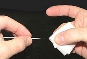
- Clean the exposed optic fiber with a rice-paper pad and isopropyl
alcohol.
Cleaving the optic fiber end
Cut the exosed fiber on both ends of the cut laser diodes—the end
connected to the LDA driver and the end connected to the LDA head.
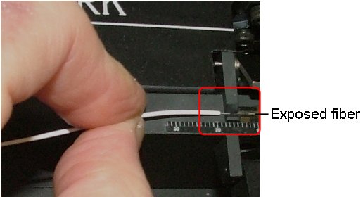
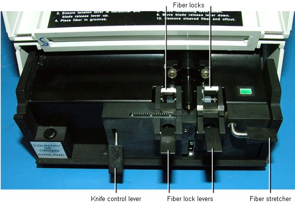
- On the cleaver, insert about 1 mm (.04 in.) of the exposed
optic fiber into the cleaver groove. The edge of the optic fiber should
be aligned on the appointed v-shaped slot.
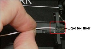
- Lock the optic fiber in place. First close the left fiber lock lever,
and then close the right fiber lock lever.
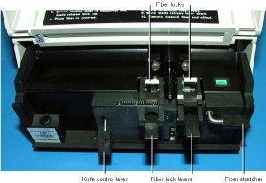
- To stretch and tighten the fiber, close the fiber stretcher.
- To cut the optic fiber, close the knife control lever.
- Remove the cut optic fiber from the cleaver:
- Open the left fiber lock lever.
- Open the right fiber lock lever.
- Lift both fiber locks simultaneously.
- Clean the optic fiber with a rice-paper pad and isopropyl alcohol,
and then lock it into position on the fusion splicer, as described in
Fusing the optic fiber ends.
Note: Before cutting the next optic fiber, remove any pieces
of fiber remaining in the cleaver.
Fusing the optic fiber ends
Fusion splicing is performed on two optic fibers simultaneously.
- On the fusion splicer, press the Program button and select
the appropriate setting according to the thickness of the fiber:
- For 30 microns, select single mode.
- For 40 microns, select single mode.
- For 60 microns, select multi mode.
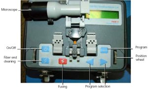
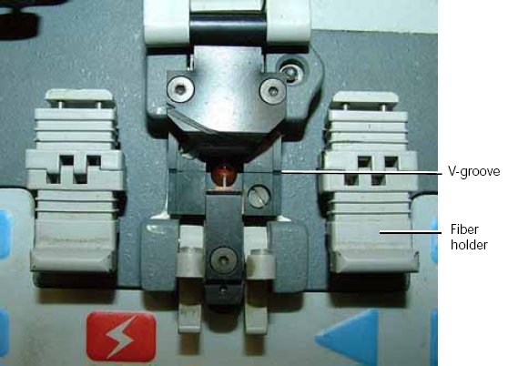
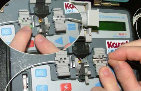
- Lift and pull back the fiber holders.
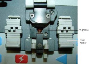
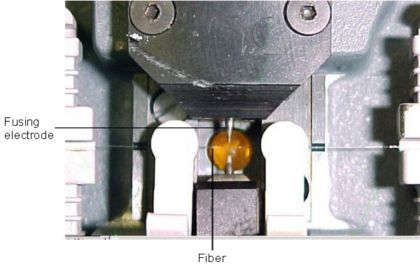
- Position the optic fibers in the V-groove on the fusion splicer. Make
sure that both fiber ends are within 1 mm from the fusion electrodes.
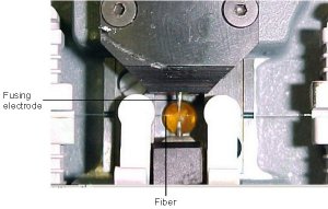
- Release the fiber holders. Verify that they touch the fiber shields
and not the exposed optic fibers.
- Lower the fiber holders to ensure that the fibers are seated properly
in the grooves.
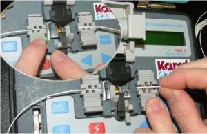
- Press the On/Off button to turn on the fusion splicer (see
step 1).
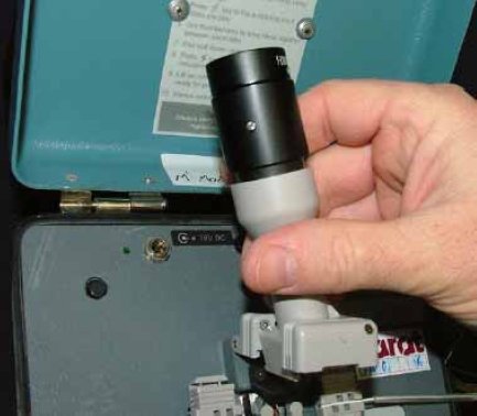
- To view the position of the fiber ends, raise the microscope.
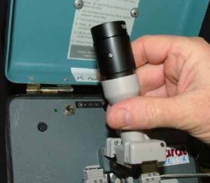
- Adjust the position wheels to bring the fiber ends into the
correct position for cleaning (see step 1).
- To clean the fiber ends,press the fiber end cleaning button
(see step 1). One cleaning is usually sufficient.
- To ensure that the fiber ends are positioned correctly for fusion
splicing, adjust the position wheels until the two fiber ends
are slightly touching.
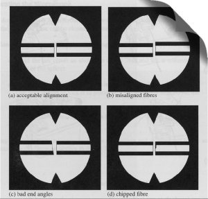
- To splice the ends of the optic fibers, press the fusing button
(see step 1).
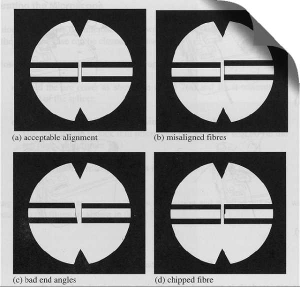
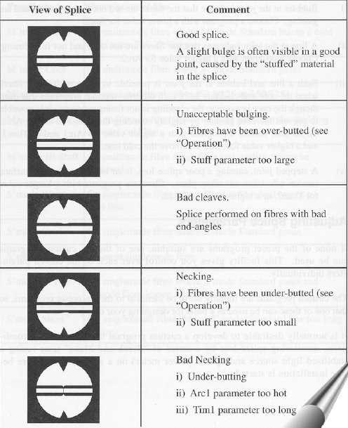
- Use the microscope to examine and confirm that the fibers are properly
spliced.
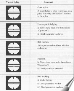
- Release the fiber holders and remove the spliced diode.
- Carefully slide the protective shrink tube over the spliced fibers.
Heating the shrink tube
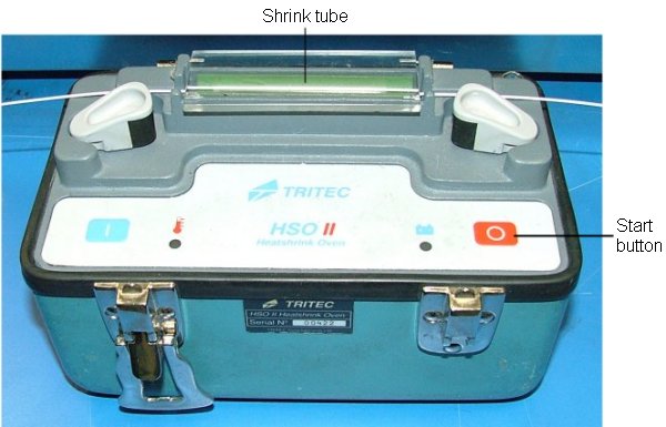
- On the heater, center the shrink tube over the heating element so
that it covers both the fused area and the sheilded fiber on both sides
of the laser diode.
- Press the start button to start the heating process. The process
takes about one minute to complete.
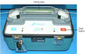
- Allow the shrink tube to cool, and then remove it from the heater.
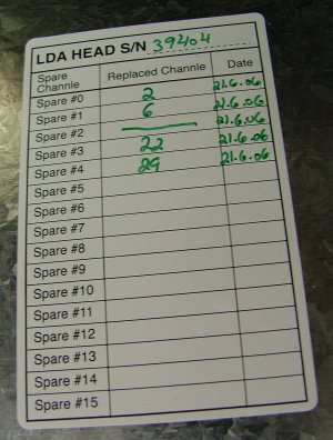
- Update the spare channel label with the replaced channel.
|