Home | Contact Us | Submit Troubleshooting Info | Search | Help


    Output | Software Solutions | Proofing | Color, Screening and Calibration | Scanning | Digital Photography | Consumables | POS


Optimizing the cassette’s position inside the Magnus 800 single-cassette autoloader S300


Product


Kodak® Magnus™ single-cassette autoloader S300


Background


The single-cassette autoloader S300 model is slightly different to previous models:

  • S300 model has only one shock absorber


  • S300 model does not have a cassette locker
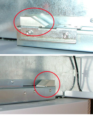
  • S300 model has two wedge-shaped stoppers. The stoppers are located on either side of the cassette runners and prevent the operator from pushing the tray too far inside the single-cassette autoloader.


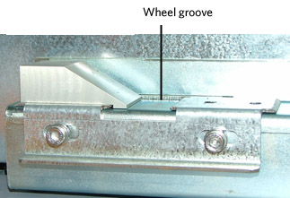
  • S300 model has a wheel groove located adjacent to one of the wedge-shaped stoppers. The groove is designed to secure the cassette wheel in its optimum location.


  • S300 model eliminates the necessity of aligning the suction cups to the suction cup holes during the alignment process.
  • When the cassette shutter is retracted, the tray on the S300 model does not self-extract from the single-cassette autoloader.


Procedure


This procedure describes how to optimize the position of the cassette inside the single-cassette autoloader S300.

Remove, and then reinsert the single-cassette trolley inside the single-cassette autoloader, and check for the following:

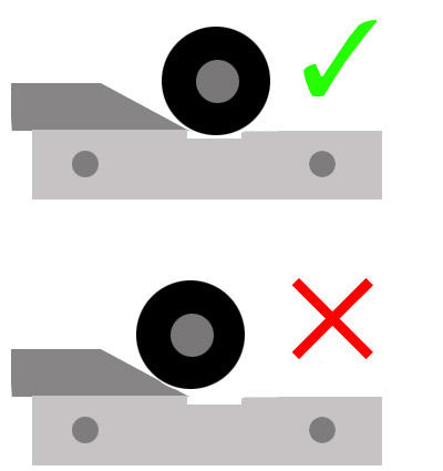
  • The cassette tray touches the shock absorber. The rebound caused when the shock absorber touches the cassette tray must not be too strong, otherwise the shock absorber will push the cassette wheel from its optimum position inside the wheel groove.
  • Cassette wheels touch the wedge-shaped stoppers, but the wheels do not rest on the incline.


  • Cassette shutter falls directly into the cassette shutter hole.
  • When the cassette tray is inserted inside the single-cassette autoloader, verify that the Cassette in place detector appears as on in Magnus 800 Controller software.

If the above conditions are not satisfied, perform the following procedure.

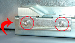
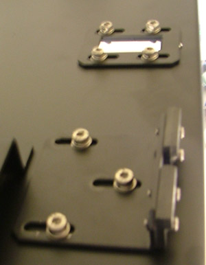
  1. Release the four screws securing the wheel groove assembly. Two of the screws are located from inside the runner.


  2. Adjust the position of the wheel groove assembly so that the wheel falls exactly in the middle of the groove, and then retighten the screws.
  3. Align the two wedge-shaped stoppers to each other.
  4. Adjust the magnets on the cassette tray so that the Cassette in place detector appears as on (when the cassette tray is inserted inside the single-cassette autoloader).


Technical contact
 

Content owner: Nir Peleg
See the Escalation page for escalation contacts.

Date submitted
 

27 May 2007


    Copyright © 2005 Creo Inc. All rights reserved. Confidential. Back to top.