|
Product |
|
- All Magnus VLF devices with serial number MT184 or lower
- All Magnus 800 devices with serial number M80364 or lower
|
|
Machines affected |
|
All Magnus VLF and Magnus 800 machines with a Thermal 2.x head and Magnus VLF or 800/TH2 carriage. |
|
Component |
|
Carriage |
|
Error |
|
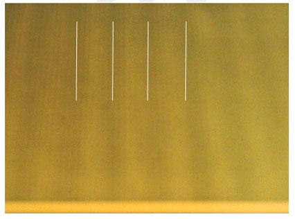
This artifact appears as a variable loss of image density that repeats every 17.9 mm in the
subscan direction. The affect is to produce vertical stripes that repeat every 17.9mm. The signature spacing is the best way
to discern this problem from traditional banding (which will repeat at the swath width). |
|
Symptoms |
|
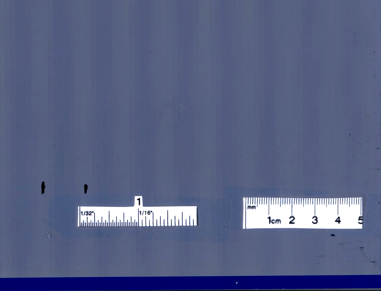
A sample photo of this problem is included here. White lines have been added to illustrate the
spacing of the artifact. Spacing between the lines is 17.9 mm.
Click for a larger image.
|
|
Cause |
|
The cause of this artifact is a combination of characteristics of the carriage bearings and the limitations of the thermal 2
head focus system. The thermal 2 head uses two lasers while imaging:
- A low power laser which is part of a range finder system that reads the distance between the thermal head and the plate mounted
on the drum.
- A powerful write laser that exposes the plate.
The lower power focus laser system is located approximately 1 mm ahead of the write
laser beam. This system collects data about the distance between the plate and the head and stores it in a table. On the next revolution of
the drum the carriage is in the position described by the table and the data in this table is used to choose a lens position that will
provide the write laser optimum focus.
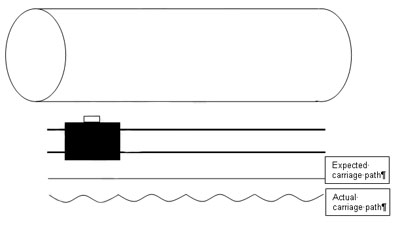
The problem is that the carriage moves relative to the drum because of the bearing’s out of round tolerance. As a result the distance
between the head and the plate that was measured by the focus range finder is incorrect because the head is in a different position
relative to the drum. The write laser requires the beam to be focused within +/-3 microns. Unfortunately the movement of the carriage
relative to the drum is around this size.
 |
|
Solution |
|
- Magnus 800 only: Using the FCO Updater Utility, confirm that carriage FCO #512-00424A was implemented. Go to Magnus 800 FCO #512-00424A
- Escalate this issue to the appropriate PD-PSS/PSM. They will co-ordinate a carriage replacement as necessary.
- Record the name of the customer, the serial number of the Magnus VLF or 800, and the thermal head that is installed.
- Take a digital photo showing an example of the artifact. Ensure that the photo shows a ruler layed over the artifact so that the size is easy to see.
- Provide as much detail as possible.
- Is the banding visible on plate or only on press?
- What is the size and frequency of the banding? Is it consistent all over the plate or press sheet?
- Do you get good results after running a media tuning? If so, what is changing during the media tuning (for example sd, laserpower, etc)?
- What is the 50% reading (Staccato 20, 3x3 and 8x8)?
- Send this infromation to your PSS/PSM.
- In the meantime complete the following steps.
Note: This artifact may tend to come and go because of the relative position of the out of round in the bearings.
- Check that the processing line is within specification and the chemistry is fresh.
- Ensure the preheat oven is configured correctly (if an oven is being used).
- The thermal head is set up with very careful attention to the surface depth series. Perform an extreme final SD series in steps of 3 microns or less. The strips that are being plotted at this time must be a minimum of 50 mm wide so that the repeating pattern of the artifact will be visible if it is present.
- Double-burn the plots (this makes the pattern easily visible). The carriage artifact is most visible in plot 7, 11 or 28 test patterns (these patterns are 2 and 3 pixel horizontal or vertical lines).
- Answer the following troubleshooting questions:
- Are you sure that this is carriage-related banding? Do the samples with banding show a similar artifact as the plot 11? Are the media settings appearing to drift? For example, are sd and slope and curve are changing over days?
- How severe is the carriage wobble? Using the lenticular tool on a plot 28, measure the wobble. For example, if you see 1-2 micron swath shifting or varying tilt from the carriage then this is within specification. If you see a shift of 5 microns or more, then it can cause banding in Staccato 20: this is not caused by the thermal head and a new head will not correct it. See the following example of horizontal lines that a head swap could not fix: Photo of lenticular analysis.
- What is the banding latitude of this head? If the head is performing within the specification of the media, do not replace the head. For example, Sword Excel at Staccato 20 has a minimum requirement of 5 banding free 3x3 strips (increment of 1) in the final slope series. If it has 5 or more banding free strips then the head is performing within specification and should not be replaced.
|
|
See also |
|
Artifact viewed using the lenticular tool (click for larger image):
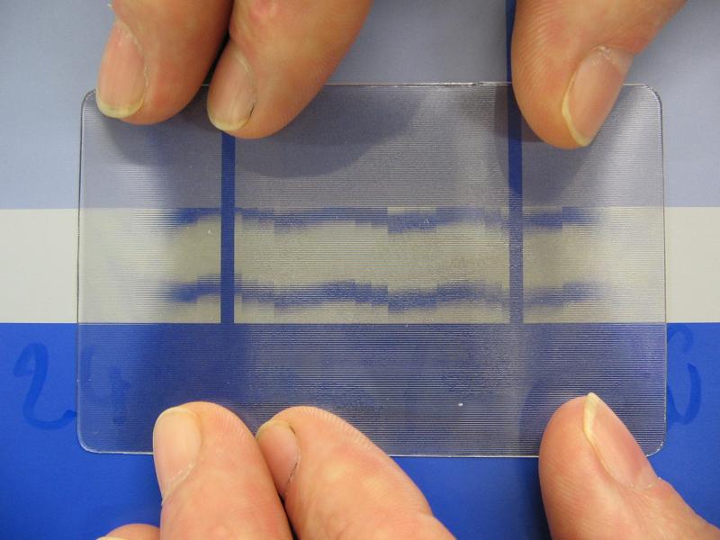
Before fix:
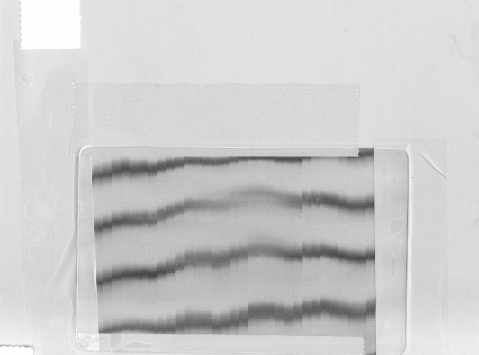
After fix:
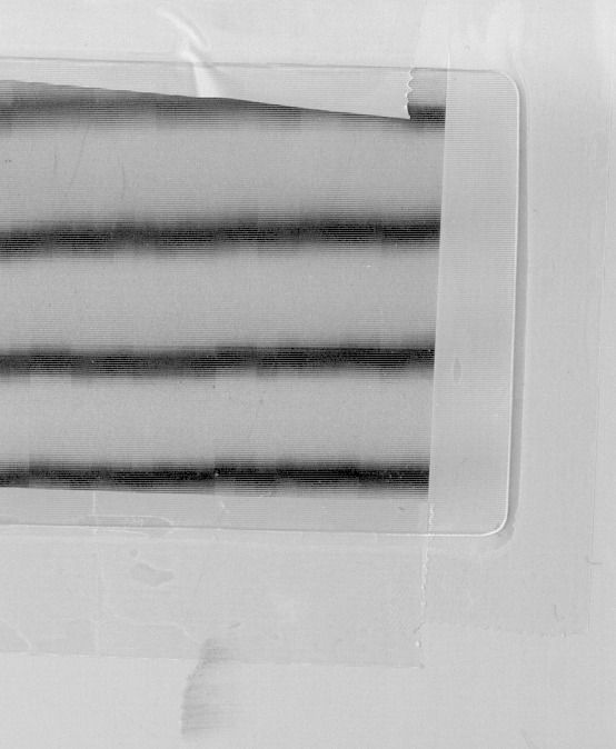
|
|
Technical contact(s) |
|
Micle Zisman (Magnus VLF)
Nir Peleg (Magnus 800)
Kyle Good (Thermal 2) |
Submitted by |
|
Doug Jeffery |
Date submitted |
|
06 Dec 2005 |

