|
Product |
|
All devices with GMCE boards. Note that this can also occur with Genine and TMCE boards, but the troubleshooting procedure will be different. |
|
Error |
|
Multiple sensors are not working. Interrupt sensors such as the home/away sensors will show “blocked” and reflective sensors will never detect something in front of them. |
|
Cause |
|
The +5v line that drives the IR LED in the sensor has a polyfuse in series to protect against short circuits in the wiring harness. The +5v is shown on the schematic as “+5v_I” where I means ‘Interface’. If the +5v_I is shorted to the frame somewhere in the device, then all sensors that are powered by the +5v_I signal will not work. It can also indicate that something is drawing too much power.
Use the gmce power command to check that the +5v_I is OK. The following is the output from this command. 5v_I is derived from AI_Check_5V so it has to be OK. From the example below, you can see that AI_5V_I shows that it is OK, it is 5V. If it was shorted somewhere, then the gmce power command would display a low voltage for AI_5V_I, probably less than 1V.
Gboot>> gmce power
GMCE voltage readings:
AI_Check_1_5V = 1.455 V
AI_Check_1_8V = 1.807 V
AI_Check_2_5VRocket = 2.500 V
AI_Check_2_5V = 2.417 V
AI_Check_3_3V = 3.306 V
AI_Check_5V = 5.117 V
AI_Check_12V = 11.953 V
AI_Check_24V = 23.870 V
AI_Check_P24V_Safe = 0.000 V
AI_Check_P48V_Safe = 0.000 V
AI_GroundDetect = 0.000 V
AI_VRef = 1.227 V
AI_Vtt = 1.226 V
AI_5V_I = 5.112 V
AI_12V_I = 11.982 V
AI_P24V_I = 24.010 V
AI_N12V = -12.021 V
|
|
Solution |
|
- Put the machine into boot mode so that it will not attempt to move any actuators. From service shell, enter the command
reset boot.
- Hit after the board starts up in boot mode. You should see a Gboot>> prompt.
- Enter the command
gmce power. Check the voltages AI_Check_5V and AI_5V_I. If AI_Check_5V is low, then the problem is the on the GMCE board itself. The AI_Check_5V is generated on the GMCE from the +24v power supply.
- If AI_Check_5V is good, but AI_5V_I is low, then the likely cause is overcurrent on the AI_5V_I line. This is the voltage that powers all sensor LEDs and other interface circuits.
- Wear an anti-static strap and disconnect the connectors that are shown in the list below. After disconnecting a cable, use the gmce power command to see if AI_5V_I returned to normal. Note that it will take about 20 seconds for the polyfuse to reset itself after the short circuit is removed.
Disconnect the sensors in the order shown below. Use the
gmce power command after disconnecting each cable.
J4 – engine sensors
J5 – engine sensors
J6 – engine sensors
J26 – carriage amp
J16 – control panel
J35 – drum amp
J24 – registration board
J30 – engine temperature
CONN9 – leadscrew temperature
J12 – plate sensor 1
J20 – tach encoder
J2 – Head control
J14 – Camera LED driver feedback (5V_I not used for now)
J21 – OK since there is a 1.2K ohm resistor in series (to registration board)
When you locate the connector that has the short circuit, refer to the wiring diagram for the device. The diagrams can be found on techplanet at: http://techplanet.creo.com/output/computer_to_plate/magnus_vlf_al/nav/dwgs-photos.htm#diag_schematic
Refer to the diagram to see where the cable goes. Most likely the cause is a pinched wire, a worn wire, or a wire that it too tight against a sharp bracket. It can also be caused by a faulty board/assembly that is drawing too much current.
Use the gmce power command as before and disconnect the individual components or assemblies until the AI_5V_I returns to normal. This can be an intermittent problem and sometimes moving a cable track or assembly may return AI_5V_I to normal. Be careful to move or disconnect only 1 thing at a time so you can narrow down the root cause of the problem. Moving something may cause the problem to temporarily disappear, only to return a few days or weeks later. |
|
See also |
|
- For details on the LED status, see GMCE Firmware and LED Reference
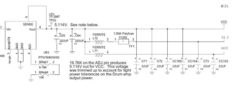
The schematic below shows how 5V_I is generated. In this schematic, Vcc is AI_Check_5V and 5V_I is AI_5V_I.
- See also Genine Board Resetting
. |
|
Technical contact(s) |
|
Al Edge |
Submitted by |
|
Al Edge |
Date submitted |
|
20 Apr 2007 |

