

Home | Contact Us | Submit Troubleshooting Info | Search | Help
Output | Software Solutions | Proofing | Color, Screening and Calibration | Scanning | Digital Photography | Consumables | POS
Home | Contact Us | Submit Troubleshooting Info | Search | Help
Output | Software Solutions | Proofing | Color, Screening and Calibration | Scanning | Digital Photography | Consumables | POS
To see the press release, go to http://graphics.kodak.com/global/about_gcg/news/2006/060404a.htm .
Drawings/photos | Dual Punch | Firmware | Parts | Procedures | Sequence of Operation | Specifications | Tools | Troubleshooting
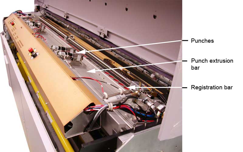
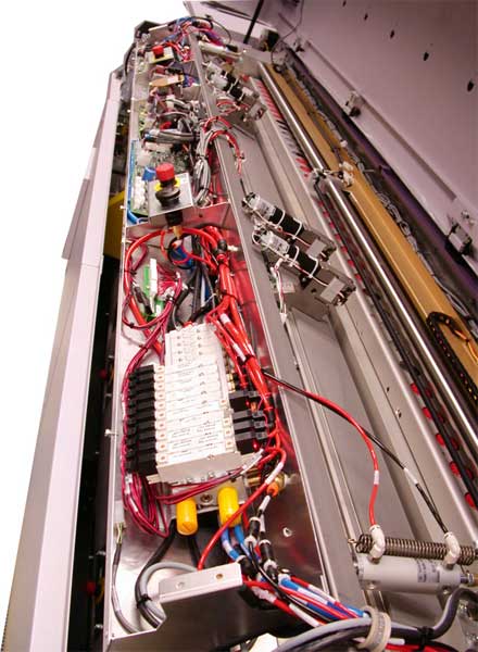
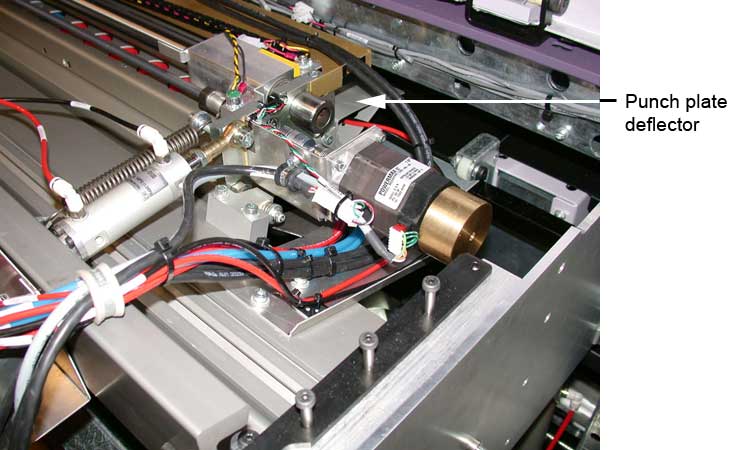
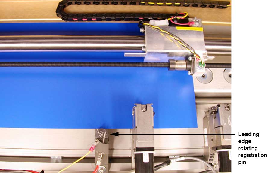
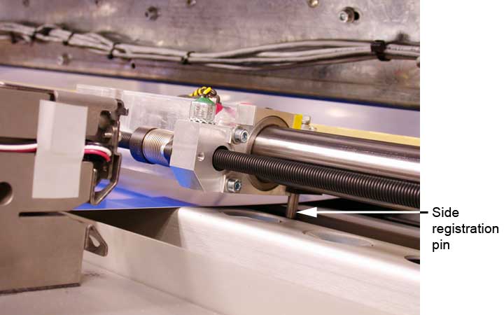
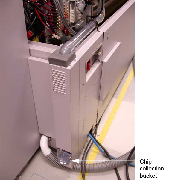
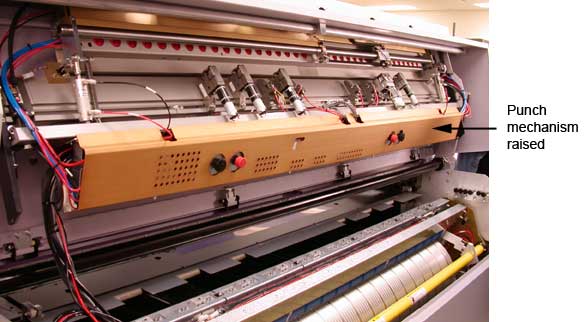
The Punch Option for the Magnus VLF punches the plates after imaging. The punched holes are customized for each individual customer. The major subsystems of the punch system are the:
This is a high level overview only. For a more detailed sequence of operation, see the firmware sequence list. The sequence of operation shown below is for punching of a single plate.
A plate is picked from the MCU, loaded onto the drum, imaged, and unloaded off the drum as normal. Once the unload table untilts and becomes level, the punch sequence starts.
In a separate sequence, to clear the punched chips that collect in the hollow punch extrusion bar, an air amplifier turns on and blows the chips into a clear plastic container mounted on the outside of the device. The air amplifier is turned on during initialization. It also runs every 60 minutes under normal operation under the following conditions:
The registration bar (500-03205A) uses vacuum cups to hold the underside of the plate to the top flat surface of the bar. This bar is
then able to bring the leading edge of the plate towards the registration pins to position the plate for punching.
The registration bar has five air bearings made of turcite that float on PEEK tape placed on the sheet metal surface of the punch
deflector pan. The air bearings give the bar low friction to help keep from buckling the edges of thinner plates when registering on the
punch registration pins. To allow for angular misalignment, a pair of pneumatic cylinder assemblies 500-03536A are mounted to the sheet
metal lip of the plate deflector with a pin and a rod end onto the registration bar. Each cylinder has a 10 mm bore x 55 mm stroke with
a special slow speed optional seal. The air supplied to these cylinders is controlled by two electronically controlled pressure
regulators (342-00075) that are located in the electronics tray of the punch unit. The pressure is controlled to each cylinder by the
device firmware based on calculated values depending on the plate size, thickness, orientation, and center offset of the plate versus
the pushing cylinders. There are NVS parameters available to set the pushing force correctly. The away side air cylinder has a spring to
counteract some of the push force that can pull the plate away from the side edge registration pin when pushing the bar laterally for
correct side register position. There are four flow orifices that control the speed of the push cylinders: two located on the pressure
regulator bodies themselves and two on the air lines going to the cylinders. The cylinders are somewhat susceptible to friction differences
from various sources. The speed at which they push the registration bar is also important. The firmware does an “exercise” routine for
the push cylinders every time it initializes the punch. This is because the cylinders have a special slow speed seal which could take a
set if sitting in one spot for too long. This exercise routine pushes the registration bar forward and back three times to ensure there
is no friction. It also does this before a punch if the firmware detects that it has not punched plate in the last 15 minutes or so.
The punch registration bar uses 36 specially designed vacuum cups made of 40 durometer silicone and 32 mm in diameter. There are four
manifolds with nine cups mounted on each (two per each half of the registration bar). The vacuum is supplied by a single high flow low
vacuum type vacuum generator (340-00001). The vacuum is fed to the manifolds via ¼ in. lines (two per side—one per manifold). The
generator is located in the center of the electronics tray to maintain an equal length of the lines. The vacuum is not modulated in any
way. The vacuum cup mounts have 0.007 in. orifices threaded into them to keep leakage to a minimum and allow a variable amount of suction
cups to be uncovered while maintaining adequate vacuum.
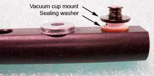
Each cup is held onto its mount by a barb type fitting on the end of the mount. The mount is threaded into the manifold and has
Teflon tape on its threads to ensure sealing. A copper sealing washer sets the height from the manifold face to the mount correctly.
Inside the mount there is a 0.007 in. brass orifice with a #10-32 thread that is threaded into the cup mount and glued using Loctite 417
(89-0180). There is also a metal screen with approximately 0.005 in. openings that should keep the orifice from getting clogged.
The Magnus VLF uses individual punch heads that are clamped to a machined extrusion using T-nut type fasteners. The punch heads have motors with cams that push the die to punch through a printing plate. To achieve proper accuracy, the punch heads are adjusted in the mainscan and subscan directions relative to the registration pins.
The Magnus VLF punch system uses the same punch heads as the Magnus 800 system and also punches the plates emulsion side up. The Magnus VLF can use the Lotem punches, which are emulsion side down, if they are the “single” punch shape type because they work even if mirrored (emulsion up vs. emulsion down). The Magnus VLF punch system can control up to a maximum of 16 motors and 5 registration pin pairs. The Magnus VLF punch system differs from the Lotem and Magnus 800 in several ways:
There are two types of variable punches (moving punches). The first is the kind that slides in the mainscan direction and the other is the kind that slides in the subscan direction. The reason these exist is when there is interference between punch shapes or bodies that cannot be fixed simply by shifting the group. In these cases, it is necessary to move the punch head. This is done by designing the punch head in 2 pieces with a precision slide and air cylinder to actuate it. The stops are machined directly into the steel bodies and are “hard” stops (the cylinder is not the end stop) to provide an accurate travel. Note that on the variable (traveling) punches there is a need to catch the chips and funnel them to the drilled hole in the extrusion without leaking too much vacuum. This is done by a custom plastic adaptor which you can see in the pictures. You should drill the hole in the extrusion according to where the hole in the adaptor will need it.
Sometimes you need to incorporate two or even more punch shapes into the same punch body. If you use just one motor to actuate the punch dies, then you can have a double punch that is usually 50 mm wide. This punch, however, does not have a round exit hole for the chips, but has a rectangular hollow section. This requires a rectangular matching hole to be made in the extrusion to keep the punch chips from accumulating and possibly jamming up. Alternatively, a chip guide chute can be inserted into the rectangular cavity of the punch body. The chute has a round exit hole to match the standard 22 mm hole drilled into the extrusion. It simply clips in place and should not be able to come out once the punch is in position.
The dual plate punching option is for customers that require both imaged plates to be punched on the Magnus VLF. The Magnus VLF punching system can only punch plates one at a time, therefore when imaging is complete, the plate farthest from the
eject side must be shuffled over to make room for the plate closest to the eject side to be punched first. Because there is more room to store a plate on the right side (away side) of the unload table than on the left side,
different hardware is installed on right eject and left eject devices to enable dual plate punching.
Dual plate punching is not supported on Magnus VLF ContinuousLoad devices. On Magnus VLF MCU and Magnus VLF APL devices, the following hardware is installed to enable dual plate punching:
Right eject devices—An extended plate support panel on the home side of the unload table and an additional kicker assembly that pushes the plate back to within reach of the ejector fingers.
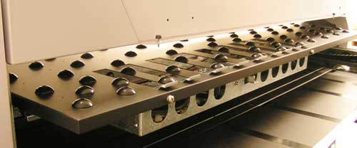
Left eject devices—An extended plate support panel on the away side of the unload table and the relocation of the ejector sensor bracket and sensor tab.
The kicker assembly consists of the kicker fingers, an air cylinder to push the kicker fingers, and two optical interrupt sensors.
The plate support panel is an extension of the unload table and has darts similar to the unload table's darts—the same spacing and height.
For parts information, see the Punch parts page.
See the Procedures page.
See the Troubleshooting page.