

Home | Contact Us | Submit Troubleshooting Info | Search | Help
Output | Software Solutions | Proofing | Color, Screening and Calibration | Scanning | Digital Photography | Consumables | POS
Home | Contact Us | Submit Troubleshooting Info | Search | Help
Output | Software Solutions | Proofing | Color, Screening and Calibration | Scanning | Digital Photography | Consumables | POS
Description | Fixes and Features | Install Time and Order | Limitations | Dependencies | Workflow Compatibility
| Component | Version | Release Notes |
|---|---|---|
| Print Console (includes TIFF Downloader 3.0) | 2.2.2.1 | Release Notes |
| TIFF Assembler | 1.2 | Release Notes |
| Copydot Toolkit Viewer | 3.0 | Release Notes |
| Service Shell | 2.3 | Release Notes |
| TFX Head firmware + Xilinx | 1.04 | Release Notes |
| ThermoFlex Thermal MPE firmware | 1.40 | release notes |
Part Number: 20-0199A-B
For general information about controlled releases, see the FAQ for Controlled Releases.
Major problems resolved are:
Purpose is to improve user experience and efficiency with:
Install in the order given. Review the Dependencies before beginning. For more information about each component, see the release notes.
Total time - 5.0 hours (minimum).
| Task | Time |
|---|---|
| Service Shell installation - needed for checking head/mpe f/w versions and for downloading the new f/w | 0.25 hour |
| To upgrade firmware, including checking head and MPE f/w versions; backup NVS parameters - fsave all; nvs dump; download new mpe f/w; nvs upgrade; checking nvs parameters | 1 hour |
| Upgrade PrintConsole | 0.25 hour |
| Upgrade Copydot Toolkit Viewer | 0.25 hour |
| Connect the diagnostic cable 16-3460B-A to the workstation. Follow the Diagnostic Cable Connection instructions below. | 0.25 hour |
| Configure Service Shell for 2 ports. Follow the Service Shell Configuration instructions below. | 0.25 hour |
Check the following MPE parameters:
|
0.25 hour |
| Check that the device and all applications are functional, including load/unload of small/medium/large size media | 1.5 hours |
| Demo and provide instructions of changes to customers | 1 hour |
One of the cables connected to the TFX head is a serial diagnostic cable, currently unused. See Figure 1 below for its location.
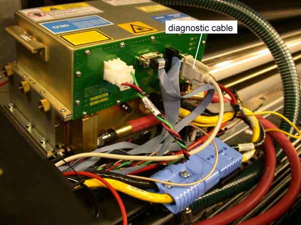
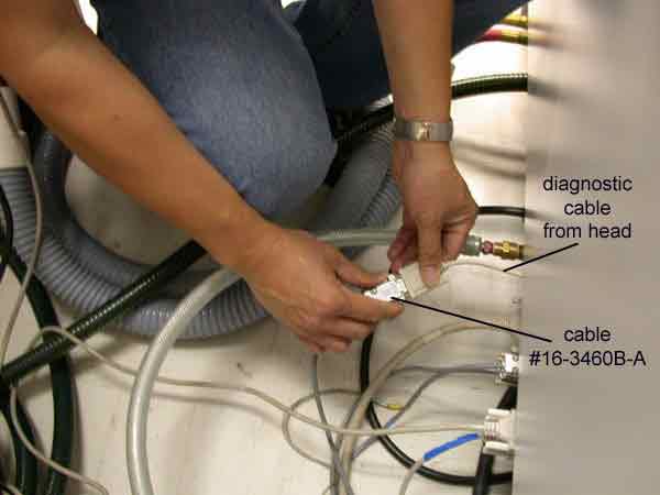
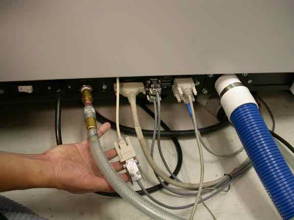
The diagnostic cable exits through the right bulkhead of the device, but is not connected to anything; it just hangs loosely. Use cable #16-3460B-A to connect the diagnostic cable to the workstation's Com4 port (P2 on the serial board), as illustrated in Figures 2 and 3 below. Cable #16-3460B-A must be ordered separately from the Controlled Release package.
++++++++++++++++++++++++++++++++++++++++++++++++++++++++++++++++++++++++++++++++++++++++++++++++++
[SystemInfo]
SystemModel=CTP
;SystemName= - name of the system to display (default to model name)
;SystemHtmlPath= - relative path of html documenation (default to model name)
[deviceinfo]
;tell the system how many devices we have
number=4
;list the names of each device
device1=WORKSTATION
device2=SRVSHELL
;uncomment the following line for an MPE-based system
device3=MPE
device4=TFX
;uncomment the following line for an MCE-based system
;device3=MCE
[WORKSTATION]
Type=WS
number=2
rconaddress=0.2.0
[SRVSHELL]
Type=SVCHOST
number=1
rconaddress=0.1.0
[MPE]
Type=Terminal
Number=1
Asciichannel=1
Monitor=ascii
[MCE]
Type=MCE
Number=1
rconaddress=1.0.0
Asciichannel=1
Monitor=ascii
[TFX]
Type=Terminal
Number=2
Asciichannel=2
Monitor=ascii
>++++++++++++++++++++++++++++++++++++++++++++++++++++++++++++++++++++++++++++++++++++++++++++++++++