Home | Contact Us | Submit Troubleshooting Info | Search | Help
Output | Software Solutions | Proofing | Color, Screening and Calibration | Scanning | Digital Photography | Consumables | POS
Home | Contact Us | Submit Troubleshooting Info | Search | Help
Output | Software Solutions | Proofing | Color, Screening and Calibration | Scanning | Digital Photography | Consumables | POS
Commands | Description | Key Features | Location | Notes | Parts | Photos | Procedures
The ThermoFlex Drum Vacuum System consists of three main components:
The Drum Vacuum System (DVS) supplies a vacuum to the ThermoFlex drum. This vacuum is to provide a constant inward seeking force on the drum that firmly holds the drum media in place. Air is drawn through vacuum holes at the drum surface and evacuated from both ends of the drum through tubes attached to hoses that are directly connected to the DVP. The drum vacuum is kept constant for different media sizes.
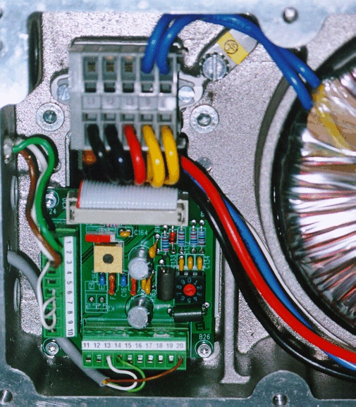
The Drum Vacuum Drive consists of an Inverter Drive Isolation Board, an Inverter Drive, a Power Disconnect switch, and a Toroid Transformer.
For part numbers, see the Drum Vacuum System Parts Page.
Input Power must be between 360-480 Vac, 50/60 Hz 3-phase. The Power Disconnect switch turns the DVS "On/Off" by either disconnecting power or allowing it to pass. The input power feeds through a RFI Line Filter which filters out noise and outside interferences which may be present on the supply voltage. The 3-phase supply feeds the Inverter Drive which in turn powers the DVP. The fan on the DVP is a single phase motor. Two of the 3-phase terminals feed the single phase Toroid Transformer, which steps down the voltage and feeds the DVP fan.
The Inverter Drive powers the DVP. The output of the Inverter Drive is a three phase voltage, variable frequency. The frequency is controlled by a control voltage that varies between 0 - 10 Vdc corresponding to an output of 0 - 100 Hz. For the Inverter Drive to run at the frequency determined by the control voltage, there must be a "run signal" present and there must not be a "fault signal" present. For operation to begin after a fault signal is detected, the fault condition must cease and a reset signal must be sent. The control signal, the fault signal, the reset signal, and the run signal enter the drive via the Inverter Isolation Board.
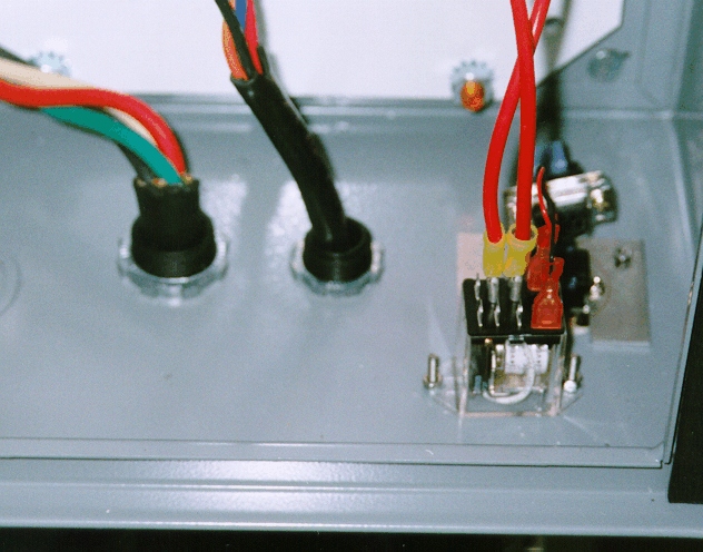
The Inverter Isolation Board is responsible for handling signals to and from the TEE board on the ThermoFlex machine. The onboard electronics on the ThermoFlex machine is responsible for the control of the DVD. The 8-bit control data, the run signal, and the reset signal are sent from the TEE board to the Inverter Isolation Board. The fault signal, which indicates that a fault is present, is sent from the Inverter Isolation Board to the TEE board. The 8-bit data sent from the TEE board is converted by a DAC to a control voltage, which is used to control the Inverter Drive frequency. The fault signal is sent to the ThermoFlex unit as long as the fault exists. Once the fault condition ceases, the ThermoFlex sends a reset command before proceeding with a run command. The fault condition to the ThermoFlex unit from the Isolation Board is generated by the Inverter Drive itself. Two contacts - MA and MC, on the Inverter Drive, are closed during a fault condition. These closed contacts drive a relay on the Inverter Isolation Board which in turn drives the signal to the TEE board. The fault condition on the Inverter drive is generated by a signal from the DVP. This signal comes from an on board temperature sensor. When the Drum Vacuum Pump overheats, the sensor which is a normally closed contact opens, indicating a fault condition. The Inverter Isolation Board also supplies power to the DVPs fan. The power to the fan is supplied by the power from the output of the toroid transformer. Power is switched through a relay to the fan. The relay is on only when the Invert Dive is running. A control signal from the Inverter drive to the Inverter Isolation Board controls this relay. Since the fan is powered by a single phase motor, a signal - out of phase with the input supply, has to be applied to the auxiliary winding. This is achieved by placing a capacitor in series with one of the input supply terminals and the starting winding.
Drum Vacuum Pump
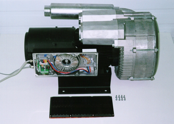
The Drum Vacuum Pump consists of a Vacuum Pump (15-1324) and a cooling fan (10-4143).
The cooling fan has a single phase reluctance motor. A capacitor in series with one of the windings supplies power to the rotor while main power supplies the stator. Without this capacitor the motor will not turn.
The Vacuum Pump is powered by a 3-phase motor. Depending on the rotation of the motor it acts as either a vacuum or a blower (generating more pressure). Switching either two of the three power terminals to the unit can change the rotation of the pump. The Inverter Drive is pre-programmed to ensure the pump operates as a vacuum. The faster the pump rotates the more air is sucked resulting in more vacuum. The speed of the Vacuum Pump can be regulated between 3000-6000 RPM or 50-100 Hz.
Drum Vacuum Sensor and Control
The Drum Vacuum Sensor and Control consists of the TEE board located behind the panels on the left side of the ThermoFlex machine. The main components of the TEE board relevant to the DVS are the onboard pressure sensor and the onboard firmware. Firmware on the TEE board handles the DVS commands for the entire ThermoFlex unit. The DVS commands are as follows:
The vacuum pump incorporates a variable frequency controlled motor and circuitry to maintain constant pressure even with varying conditions in the system. This allows media of various shapes and sizes to be held with the same amount of force.
The vacuum level is firmware controlled using a pressure sensor inside the recorder as feedback to the drum vacuum pump inverter drive.
Drum vacuum location varies depending on site conditions. Must be within 50ft of hose/cable length.
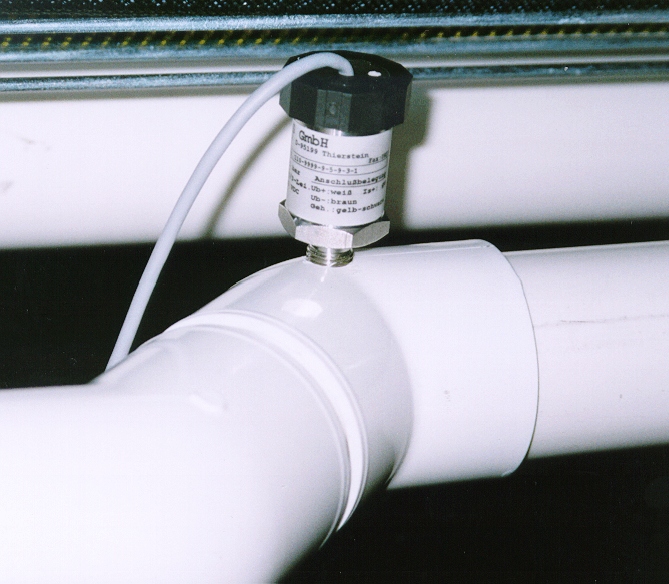
The pump’s vacuum sensor is located in the vacuum piping.
Early ThermoFlex machines were capable of turning on/off the vacuum pump via a relay in the starter unit. On these units the drum vacuum level is set by a potentiometer within the pump’s electronics box. The same vacuum level is applied to all media types.
Later ThermoFlex machines applied a control signal to the pump to adjust the vacuum level and turn the pump on and off. The starters attached to these pumps contain no Creo components.
Drum vacuum pump
Vacuum pump
pressure level adjustment; Internal potentiometer
AC power relay
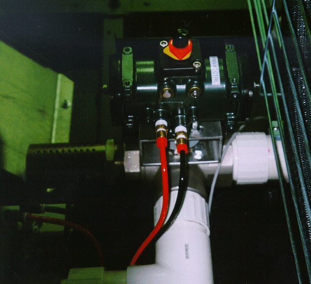
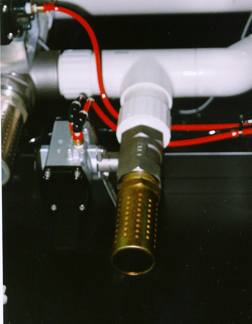
Vacuum flow diverter
valve
Vacuum relief valve
(5280 models)
Vacuum pump pressure
sensor
Quick disconnect coupling; used
in drum vacuum system piping
Drum Vacuum System Installation
Installing Drum Pin Vacuum Seals
Drum Vacuum Drive Manual Verification
Drum Vacuum System Operation
BOM
Replacing Drum Vacuum Seals
BOM