Home | Contact Us | Submit Troubleshooting Info | Search | Help


    Output | Software Solutions | Proofing | Color, Screening and Calibration | Scanning | Digital Photography | Consumables | POS


Field Change Order C953

Applies to:    Trendsetter 3244 Priority = Next visit
                      Trendsetter Spectrum Reason = Design
                      Proofsetter Spectrum Release date = 10 June 1999

Machines affected

Component

EMI emission standards
Problem An existing TS3244 machine with a 1.7 head does not satisfy European EMI emissions standards.
Solution(s) New parts were designed to fit the existing machine in order to reduce EMI emissions. The retrofit requirement applies to all TS3244 machines with a 1.7 head.
Parts needed 50-1777A
Procedure Replace Hot Link Cable
  1. Turn off the power to the output device.
  2. Remove the rear panel and power box access panel from the Trendsetter.
  3. Detach the thermal head flex track, power box flex track and hoses to facilitate the removal of the existing cable tray and hot link cable.
  4. Detach the hot link cable from the thermal head and MPE board and remove.
  5. Install the new thermal head hot link cable (10-4015A) in the flex track and connect it to the thermal head.
  6. Run the other end of the hot link cable along the inside wall of the power box wall, tying it to the existing cable harness with tie wraps. Leave the end of the cable loose (to be attached at the end of this procedure) on the floor of the power box below the card cage.
  7. Attach the MPE hot link cable (10-4106A) on the MPE board and run the other end across the bottom of the card cage and through the side of the card cage. Leave the end of the cable loose (to be attached at the end of this procedure).
  8. Remove the existing cable tray and retain the hardware.
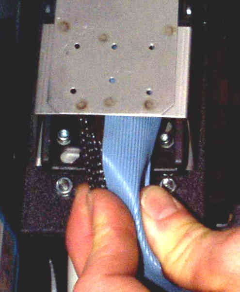
  9. Using the existing hardware, install the new cable tray (57-2218C).
    See photo 1.

Install Cable Tray-to-Head and Cable Tray-to-Power Box Bonding Straps

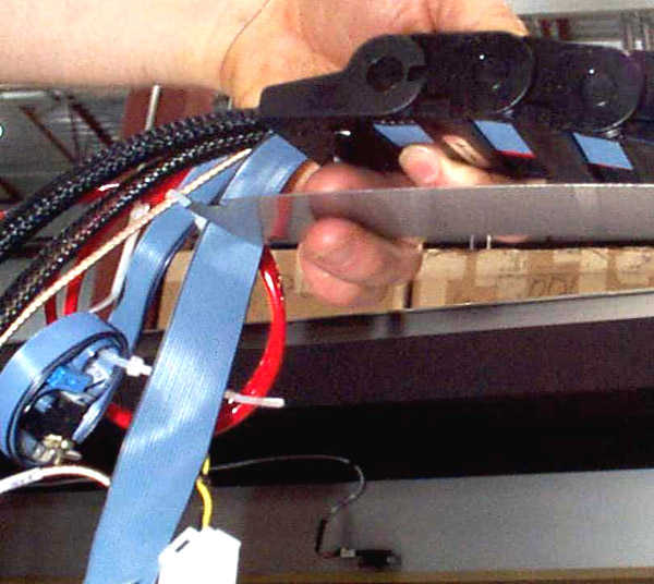
  1. Using existing hardware, follow the steps below to mount the bonding straps to the flex tracks and cable tray. See photo 2.
    • Sandwich the tabs of the cable tray/head bonding strap (57-5974A) between the head flex track and the cable tray. The bonding strap should be on the inside curve of the flex track.
    • Sandwich the end of the power box/cable tray bonding strap (57-5973A) between the cable tray and the power box flex track. The bonding strap should be on the outside curve of the flex track.
    • Secure using existing hardware.
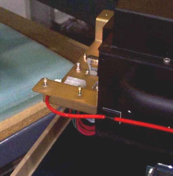
  2. Using existing hardware, mount the other end of the cable tray/head bonding strap to the thermal head mounting bracket, sandwiching the bonding strap between the flex track and the bracket. See photo 3.
  3. Using existing hardware, mount the other end of the power box/cable tray bonding strap to the tab on the power box, sandwiching the bonding strap between the flex track and the tab.

Install Card Cage Bonding Strap and Attach Hot Link Cable

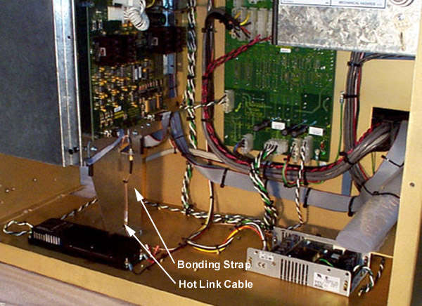
  1. Using the fasteners in the kit, install the card cage bonding strap to the card cage and the bottom panel of the power box. See photo 4.
  2. Insert the end of the MPE hot link cable through the tab hole on the card cage bonding strap from above.
  3. Attach the thermal head hot link cable to the MPE hot link cable at the tab on the card cage bonding strap.
Action Required Mark as change #19 on the ECO/100 label for Trendsetter 3244.
Mark as change #4 on ECO/100 label for Proofsetter Spectrum.
Date submitted 10 June 1999
Date modified 21 June 1999

    Copyright © 2005 Creo Inc. All rights reserved. Confidential. Back to top.