Solution |
|
- Bypass the interlock system using the SIO keyswitch.
- Move the drum to a safe position for putting the TECs on the drum.
- Move the TEC backbone onto the drum.
- Turn off the air pressure at the air regulator.
- Open the front door to access the TEC lock/unlock mechanism.
- Push on each side of the TEC lock/unlock mechanism to see whether the TEC lock/unlock sensor mounting screws are tight.
Note: If the screws in the sensors or those in the rectangular metal block are loose, either the metal tab will hit the top of the 2 mm hex screws, or the cylinder will not move freely.
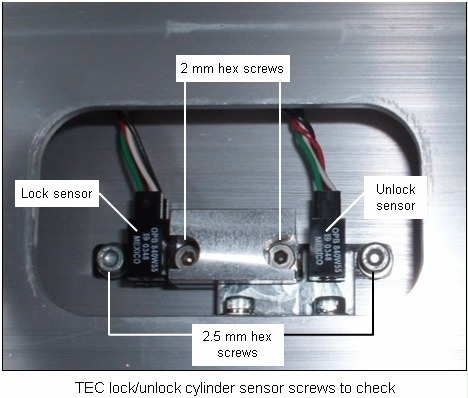
- If the sensor mounting screws are loose, proceed to step 8.
If the sensor mounting screws are tight, proceed to step 10.
- Tighten the lock sensor screws:
- Tighten the 2.5 mm screw located on the plastic part of the left side of the lock sensor.
Caution: Do not overtighten, or you risk breaking the plastic.
- Tighten the 2 mm hex screw on the right side of the lock sensor.
Note: There is no adjustment necessary on the lock sensor.
- Tighten the unlock sensor screws:
- Slide the loose unlock sensor all the way to the right.
- Tighten the 2.5 mm hex screw on the right side of the unlock sensor.
- Tighten the 2 mm hex screw on left side of the unlock sensor.
- When the screws in the lock/unlock sensor mechanism are are tight, test the sensors to ensure they are working correctly:
- Slide the cylinder to the lock position (all the way to the left).
- Go to the diagnostic monitor screen in Service Shell, and in the command box, enter command:
tec
The lock sensor should read true, and the unlock sensor should read false.
- Slide the cylinder to the unlock position (all the way to the right).
- Again, enter command
tec.
The unlock sensor should now read true, and the lock sensor should read false.
- Move the cylinder 1 mm from the unlock position to the left, and enter the
tec command again.
The unlock sensor should still read true, but beyond 1 mm to the left of the unlock position, it must read false.
- If the lock/unlock sensors are correctly adjusted (as tested in step 10), proceed to step 12.
If the lock/unlock sensors are not correctly adjusted, loosen the unlock sensor and move it 1 mm to the left. Then, repeat steps 9 and 10 until the sensor reads true for only 1 mm (+0.5 /-0 mm) of travel.
- Actuate the lock/unlock cylinder a few times to ensure that it is now working correctly. If it still fails to lock or unlock, see TECs fail to lock or unlock.
|

