Procedure
|
|
Clean the strainer, check the coolant
level and oil the pump if necessary:
- Turn off the power to the output device.
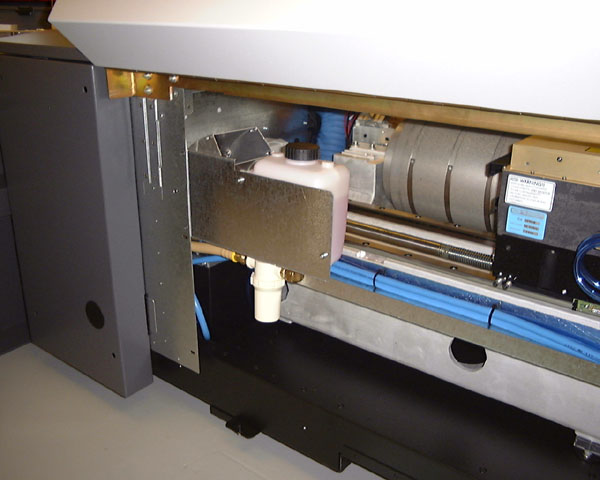
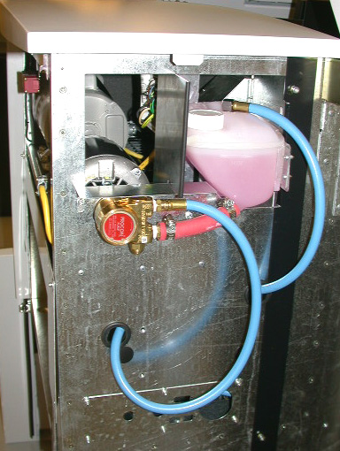
- Access the reservoir through the rear dress panel fan box
side (see photo).
- If you have the TS8 (100 label #16) or TSM style of fan box (see photo),
remove the 2 screws on the angle bracket that hold the
reservoir in place and tip the reservoir out of the opening
to access the black input cap with the quick disconnect
fitting.
- Remove the quick disconnect input line.
Remove the input cap-using a 3/4" open end wrench, if
required.
- Check coolant level in reservoir and top up with 60-40
ethylene glycol if necessary.
- Pull the strainer from the underside of the cap. Clean the
strainer using compressed air blowing from the outside
towards the inside. (Or rinse strainer in running water.)
- Replace the strainer firmly into underside of cap. Replace
the cap in the reservoir-hand tight. May have to use a
wrench if o-ring friction prevents tightening.
- Make sure the release tab, marked CPC, on the female quick
disconnect fitting is pressed in and the fitting is ready to
accept the male input fitting. Snap the input fitting into
place with the hose leading from the rear of the reservoir (
away from the drum).
- Put the reservoir back in place in the fan box, and replace
the angle bracket.
- Oil the pump motor on a yearly basis. Pry off the 2 plastic
caps; fill each with a teaspoon of SAE 10W oil and recap.
Nothing has to be done to the pump itself.
- Start the machine to make sure there are no obvious leaks.
Before leaving facility!!! Especially on black input cap.
|