Home | Contact Us | Submit Troubleshooting Info | Search | Help
Output | Software Solutions | Proofing | Color, Screening and Calibration | Scanning | Digital Photography | Consumables | POS
Home | Contact Us | Submit Troubleshooting Info | Search | Help
Output | Software Solutions | Proofing | Color, Screening and Calibration | Scanning | Digital Photography | Consumables | POS
Description | NVS parameters |
Parts | Procedures | Theory
of operation
DANGER
The encoder contains a class IIIb 2 mW infrared laser (780 nm). The
laser is not switched by door interlocks: the laser is on whenever the recorder
power is on. Do not remove the encoder block and look directly into the laser.
Do not insert anything reflective between the laser and encoder disk. Turn off
the recorder power and disconnect the cable if you must remove the encoder
block.
Measures the position and direction of motion of the drum. The speed is derived from the position information. The information from the encoder is used by the drum servo to control drum speed and by the imaging logic to synchronize image data with the plate position.
Note: This encoder is used in the Trendsetter 3244 (TS3 and some TS3/8 Versions). It is different from the encoder on newer output devices such as TS4, TS8. This encoder is optical rather than mechanical.
DRUM module: maxdiff (VLF engines only)
Encoder block | Encoder board | Encoder cover | Glass disk
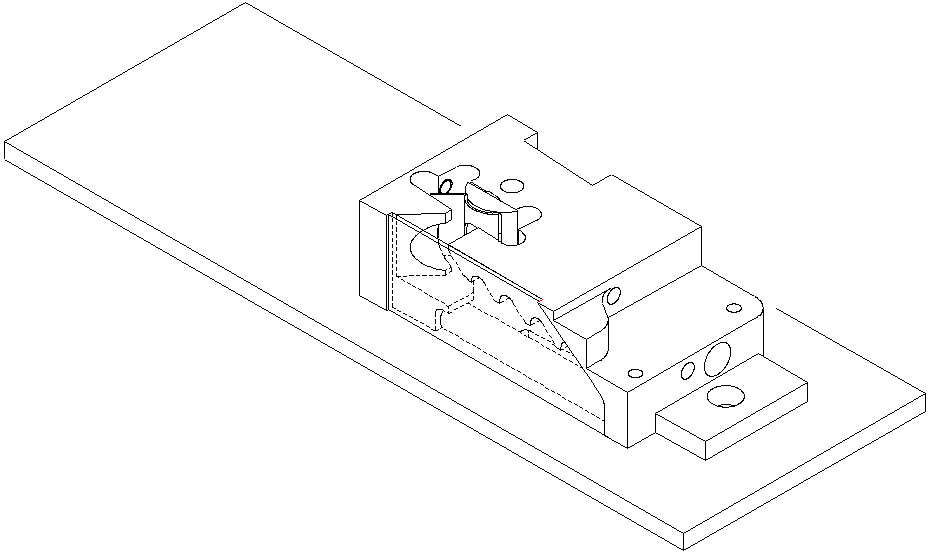
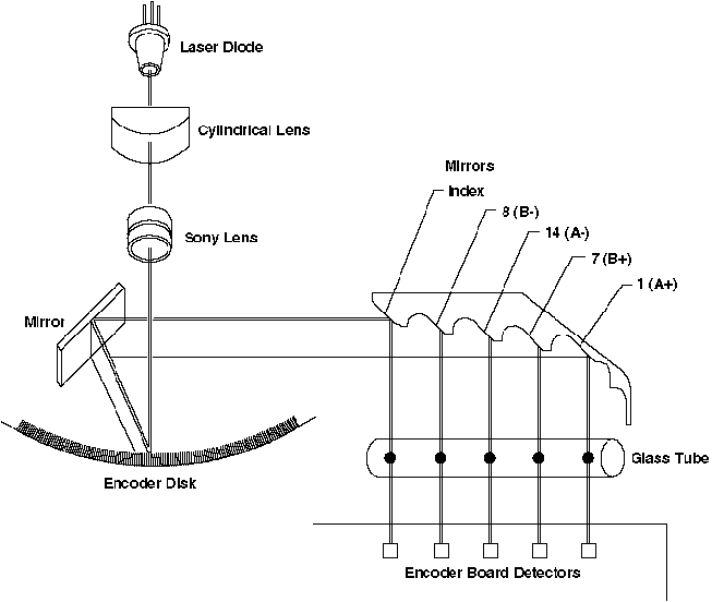
Mounted on the encoder board. Includes a laser diode and optics. The beam from the infrared is directed at the disk. The light reflected back from the chromium lines on the disk is directed sideways by a mirror in the encoder block. It is then split by five small mirrors which direct each of the five beams to one of five detectors on the encoder board named A+, A-, B+, B-, and I.
Encoder board (10-0505)
Detects the light reflected by the chromium lines to determine the drum position and direction of rotation. The information is transmitted to the MPE.
Encoder cover (57-1178)
Glass disk mounted on the end of the drum
34-3099 (large encoder disk for 5080/5880 engines)
34-3014 (small encoder disk for 3244 engines)
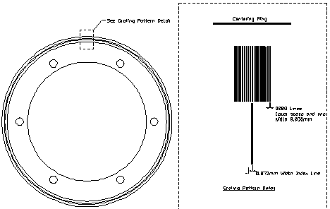
The glass disk has 9000 plated chromium lines on it. One of these lines, the index line, extends further toward the center.
Optical Encoder Alignment Procedure
Checking the optical encoder
Optical encoder cleaning procedure
Checking the PLL lights on the MPE
Signals processing
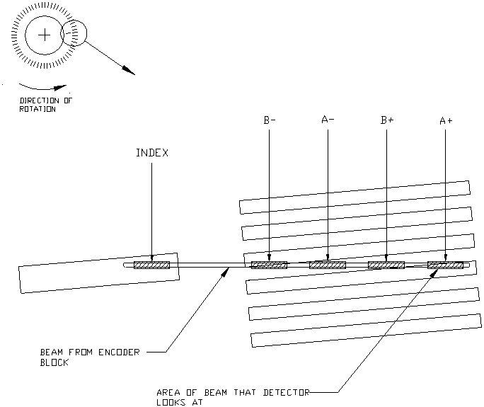
The encoder block is mounted so that the horizontal illumination line from the laser diode crosses the disk pattern. The height of the block is adjusted so that the A+ and A- detectors look at the disk at points 1/2 of a line spacing apart. Normally one of the detectors is over a chromium line and the other is not. The signals from these two detectors are subtracted and compared.

The AD signal is the difference between the A+ and the A- signals. A signal is generated if A+ is larger than A-.
The B+ and B- detectors look at the disk in the same manner as the A+ and A- detectors, but are located 1/4 of a line spacing offset from A.
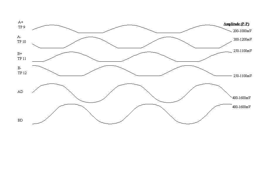
The SA and SB signals are digital signals derived from AD and BD. If SB lags SA by 90 degrees, the drum is moving forward. The signals can be adjusted so that SA and SB are 50% duty cycle.
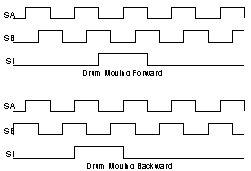
SA, SB, SI timing
The output of the encoder block electronics consists of three digital timing signals:
- SA, a high-speed square wave
- SB, a high-speed square wave
- SI, a square pulse which occurs once per drum revolution
The SA, SB and SI signals on the encoder board are inverted versions of the A, B and I signals on the MPE.
In order for the encoder to work properly, these waveforms must have a specific relationship to each other. The timing of the rising and falling edges are most important; the other parameters of the waveform (amplitude, frequency, jitter, etc) are less important.
When the unit powers up, the drum is in an arbitrary position. The electronics rotate the drum slowly, looking for the index mark on the encoder disk. The index mark uniquely identifies one of the 9000 ticks as Tick #0. Once Tick #0 has been identified, the drum position is thereafter determined by counting up ticks for forward drum rotation, and counting down ticks for backward rotation. In the forward direction, the drum rotates clockwise when viewed from the encoder end.
The oscilloscope shows the details of what happens:
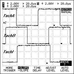
The following description is for a drum rotating forward. To see what the oscilloscope trace looks like when the drum is rotating backward, look at this figure in a mirror.
When the encoder block detectors see the index mark, the SI signal goes high. A high SI triggers the other electronics to expect a falling edge on SB. If it doesn't find one, it reports the error "Missing Index". The ideal position for the rising edge of SI is right in the middle of when SB is high. Strictly speaking, the rising edge can be as far left as the rising edge of SB, or as far right as 50ns before the falling edge of SB. However, these positions leave no room for drift.
When the electronics finds the falling edge of SB, it knows it has found the start of Tick #0. While SB is low, the electronics looks for SA to change state. If SA transits from low to high, the drum is rotating forward; if SA transits from high to low, the drum is rotating backward.
Optimum transition point for SA
SA should go high or low right in the middle of when SB is low. Strictly speaking, the rising edge can be as far left as the falling edge of SB, or as far right as 50ns before the falling edge of SI. Right in the middle allows maximum possible room for drift.
Optimum transition point for SI
SA changing state defines the end of Tick #0. The SI signal should now go low, so that the electronics stops looking for Tick #0. If SI stays high too long the electronics might see Tick #1 (the next falling edge of SB) and misinterpret it as Tick #0. The ideal position for SI to transit low is right in the middle of when SA is high or a little earlier.
The rising and falling edges of SI are changed by adjusting I Bias. Unfortunately, I Bias adjusts both edges together: it is not possible to adjust the position of the SI pulse left or right. You have to adjust I Bias to get both the rising and falling edge as optimum as possible. Both edges are equally important since the rising edge in forward rotation is the falling edge in backward rotation.
Optimum transition point for SB
During rotation away from the index pulse, the optimum timing relationship between SA and SB is 90 degrees out of phase: a transition of SB is expected while SA is stable high or low. Therefore, the ideal position for SB transitions is right in the middle of SA being stable high or low. Similarly, a transition of SA is expected while SB is stable high or low. Therefore, the ideal position for SA transitions is right in the middle of SB being stable high or low.
Dust
If a few of the ticks on the encoder disk are slightly scratched, the SB and SA timing might be momentarily incorrect. The Phase Locked Loop electronics which analyzes the SA and SB signals can correct occasional errors of this kind. However, if this occurs too often, the electronics report a "PLL Error". This could be caused by scratches or dust; cleaning the encoder disk will sometimes help.
However, you should always also check the timings between SA, SB and SI. If they have little margin for error, the encoder disk will always be extremely sensitive to dust.