Home | Contact Us | Submit Troubleshooting Info | Search | Help
Output | Software Solutions | Proofing | Color, Screening and Calibration | Scanning | Digital Photography | Consumables | POS
Home | Contact Us | Submit Troubleshooting Info | Search | Help
Output | Software Solutions | Proofing | Color, Screening and Calibration | Scanning | Digital Photography | Consumables | POS
Assembly Drawing | Description | Part Number | Connectors | Indicators | Photographs | Wiring Diagrams
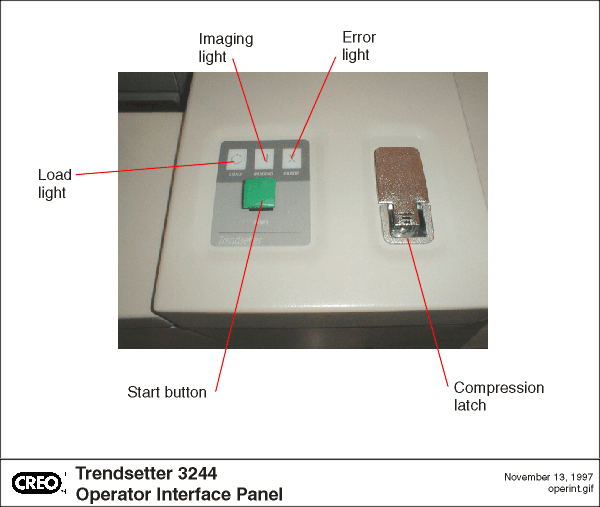
Connects to operator interface panel and provides status information for operator including:
10-1420A
| Connector | Description | Cable Name | Part number |
| J1 | 4 PIN PCB HDR, MATE-N-LOK | START BUTTON | 10-3187A |
| J2 | 14 PIN, ST PCB HEADER,POL,LATCHES | OIF-TIF | 10-3188A |
| Light | Color | Description |
| DS1 | GREEN | ready - solid |
| DS2 | GREEN | loading - flashing |
| DS3 | YELLOW | Imaging a plate -solid |
| DS4 | YELLOW | Imaging a plate - flashing |
| DS5 | RED | error -solid |
| DS6 | RED | error- flashing |