| Procedure |
Upgrade the firmware and activate
double plate detect:
- Update the firmware to Version
1.20 .
- Read the release notes first, not after you have problems.
- Enable the double plate detect in the >>SET MEDIA
"x" parameters.
- To test the double plate detect, manually load 2 plates and
try to plot.
- After the test, in Procomm capture a >>LIST STATS and
email it along with the machine serial number to smontague@creo.com
Installing the plate ledge teeth and unload air jets:
The present air knife (tube) is mounted to the plate ledge by a
number of black plastic clips. This upgrade replaces two of these
clips with deflector brackets under the ledge and teeth on top of
the ledge.
- Open the operator door. Turn the laser safety key in the
power box to mechanical hazards.
- Enter >> SET AL PCS 0 to disable the bay door sensor
so that you can move the picker around.
- Enter >>PICKER UP, then >>RAMP IN.
- Cut the tie wraps holding the air knife to the ends of the
plate ledge.
- Unsnap the air knife out of the clips with a downward jerk.
- From the right hand side of the table, count over 4 clips
and unscrew that clip from the ledge.
- From the left hand side of the table, count over 5 clips and
remove that clip.
- Lower the plate ledge by 2mm:
Place a ruler on the plate ledge and mark a point 100mm
up on the table with a pencil. Repeat for the other end. Now
loosen the counter sunk screws that hold the ledge on and
loosen the two bay door bumpers that also hold the ledge in
place. Then move the ledge down until your ruler shows 102mm
on both sides. Retighten. Do not use Loctite.
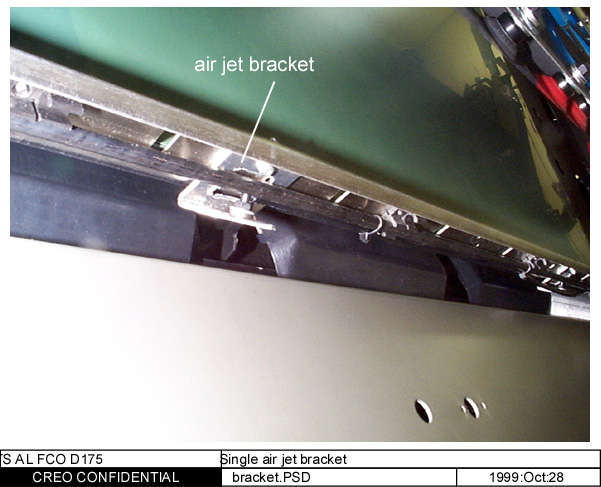
- Fasten the air jet bracket up from the bottom of the ledge
using a M3x8 screw and heavy washer (there are extra in the
kit). Don't overtighten the screw as it will bend the ledge
teeth. The jet should be angled down toward the load ramp.
Helpful Photos:
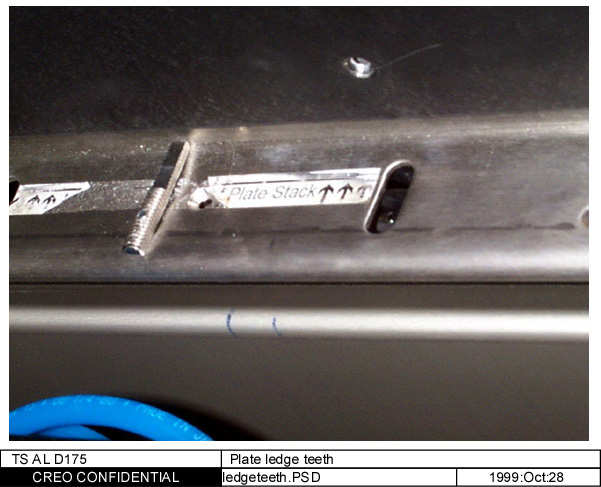
Fig 1: Plate ledge teeth
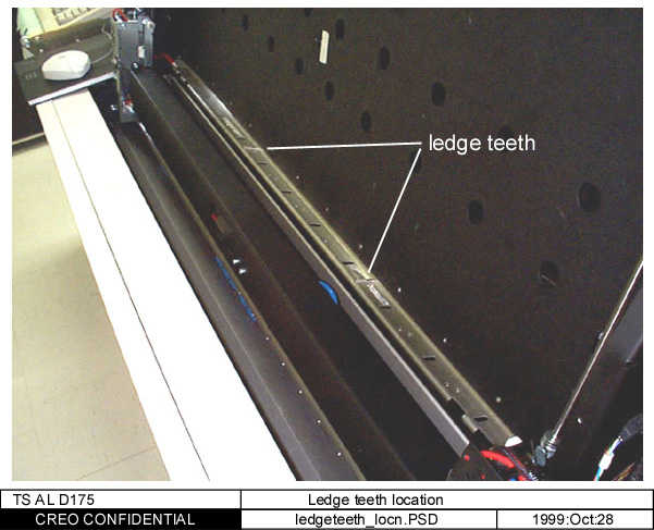
Fig 2: Location of
teeth on the plate ledge
Fig 3: Photo of
single air jet (N95) from under the ledge
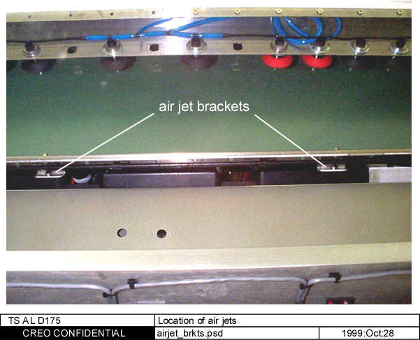
Fig 4: Location of air
jet brackets
Note: For TS3 machines the tubing
coming from the unload air jet brackets should be heading
toward the RIGHT of the machine (where the manifold is
located).
For TS3/8 and TS4 machines the tubing coming from the
unload air jet brackets should be heading toward the LEFT of
the machine (where the manifold is located).
- The M3x8 ( see step 7) screws up into the plate ledge teeth
(milled down M6 screw thread). Be sure to use Loctite 222
(10-3334) or you will be visiting this site again soon. In
some cases you may have to file the hole in the ledge just
slightly.
- Zip tie the unload air jet tubing along the air knife and
reinstall the air knife. Tie wrap the air knife to the ends
of the plate ledge. Use >>PICKER AJET ON to make
sure that the center of the air jets are angled backward,
hitting the load table 3 inches above the plate ledge.
- Route the tubing through the hole in the bottom of the load
table post by the separator arm on the right hand side for a
TS3 (left hand side for TS3/8 or TS4). Continue to the
engine manifold. Make sure that the tubing is clear from any
moving parts.
- Enter >>RAMP OUT.
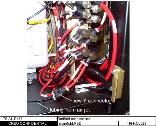
- The unload air jets connect to the upper ramp cylinder RED
tubing with a "Y" fitting at the manifold. For
machines with manifold on the right, see photo Fig
5 N95 connection at the engine manifold. For machines
with manifold on the left, see photo Fig
6 N95 connection at the engine manifold.
Disconnect the RED upper ramp cylinder tube from the
manifold. Connect the short length of tube exiting the
unload air jet tube "Y" quick connect into the
manifold. Now insert the ramp cylinder tube into the
"Y" quick connect. When the ramp is
"in", some air is also diverted through the air
jets. Various fittings are supplied since early machines
used 1/4" tubing instead of 5/32". Use what you
need.
- Test that the connections are correct by entering
>>RAMP IN, air should be blowing down the face of the
load ramp. When the RAMP is OUT the jets should be off.
|