| Procedure |
Note: References to right and left in this
procedure assume you are in front of the device, facing the picker,
that is, right = home, left = away.
- Back up the current firmware and then download Version 1.40
- Remove the right horizontal cover. ( Move the unload TABLE
DN to get the cover off.)
- Remove the right vertical post cover on the load table.
- Move the PICKER UP and then PICKER IN.
- Locate the bracket that the bottom of the RIGHT wrist
cylinder attaches to. Attach the wrist sensor (10-3676A) to
it with an M3 x 14 socket cap screw, flat washers and a
Nylock nut. The sensor should be "sensing" to the
right and be flush with the side surface. Mount the sensor
in the extreme end of the slot in the bracket so the sensor
is as close to the load table as possible. See Detail A on
page 7 of the 50-1760A picker head assembly drawing
and associated BOM.
- Attach the Wrist sensor cable 10-4579A to the optical sensor
and route the cable through the cup bar and following the
blue vacuum tubes out the square opening.
- Continue routing the cable through the picker head until
finally exiting out the cable track. Make sure the cable is
adequately tied away from any moving parts that may rub on
it.
- Move the PICKER OUT and PICKER DOWN.
- Move the unload table to the TABLE UP position, and lock in
place by putting a large allen key through an open pivot
hole.
- Disconnect the air from the machine.
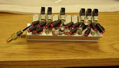
- The current manifold that you have should look something
like this :
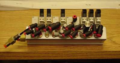
and the fittings that you are going to add look like
this:
- Unscrew the upper fitting from the manifold that is for the
plate pusher "aka, picker blow". On some machines
this will be an 8mm elbow fitting.
- Rotate the "picker move" speed control so that it
is pointing upward.
- Unscrew the lower Plug for the plate pusher. Be sure to use
an Allen key WITHOUT a ball end to remove
the brass plug. Stripping this part means ordering a new
$1200 manifold.
- Screw two 1/8 npt x 5/32 hose BRASS quick connect fittings
into the plate pusher locations. Use an imperial allen key
through the quick connect end of the fitting to screw it in.
- If you have a Kiel built machine, then you have a bit more
work to do.There are speed controls mounted under the black
horizontal cross bar (that the vacuum generator is attached
to) that control the speed of the wristing action. These
need to be removed and straight sections of tubing put in
their place. I have included some unions and tubing in the
kit so you can do this. Next, the fittings on the manifold
for the picker wrist need to be swapped out with the ones
provided with the kit. The provided fittings are actually
fixed orifice speed controls, they are chrome plated and
should have a 0.1 stamped on them. Another fixed orifice
speed control needs to be added inline with the upper
fitting. Note the direction that the fixed orifice is
pointing. (see photo in step 15).
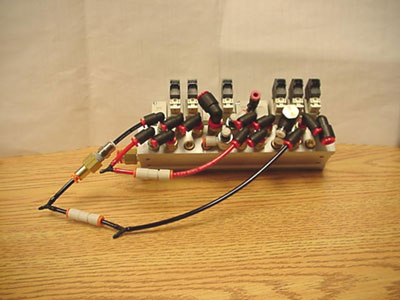
- With the fittings provided, build the tube structures by
referencing the photo.
Note the direction of the check valves for correct
operation. See sheet 9 of the drawing 50-1760A picker head assembly drawing.
Note that the fixed orifice that is "in-line"
with the black wrist tube should have a 0.2 stamped on it.
When looking at the schematic, Port "A" refers to
the upper fittings and "B" refers to the bottom
fittings on the manifold.
- Label the tubing just before the Y connectors
"Wrist" and "Head".
- On a TS4 or TS8 machine, the new cable you just put in
the picker extends the cable that is currently attached to
the "upper right, picker up" optical sensor.
Note: References to right and left in this
procedure assume you are in front of the device, facing the picker,
that is, right = home, left = away.
Unplug the upper right sensor and plug in the new cable
you just routed through the picker (see photo below).
If you are upgrading a TS3 or TS3/8 machine (TEE board is on
the right hand side of the machine instead of the left),
then the wrist sensor should plug into the picker up sensor
on the LEFT hand side of the machine. To do this you will
need to pull the left picker up sensor cable through the
lower channel in the load table so that it is on the right
hand side of the machine. Coil up the extra length of cable
in a convenient area. Plug in the new wrist sensor cable.
- Turn the air back on. Type PICKER to test the new wrist
sensor. The wrist sensor should read
- False when the picker head is out
- True when the picker head is in and the wrist is out
- False when the head is in and the wrist is in.
- Test all of these cases. Ensure that the sensor has a good
margin of detection by rotating the sensor left and right
and in and out with a signal still being detected.
- The firmware now counts how many failures are occurring with
the picking operation. Look at "SET STATE AL" for
a list of the counters to determine the health of the
machine.
- Ensure that the double plate detect is functioning properly
by manually loading two plates. If it is not working, read
the firmware release notes for V1.20.
- Email smontague@creo.com
the "total images run" and "number of
multiple plate detects" as seen in LIST STATS .
- Find the 100 label number on the left side of the machine on
the unload table frame. You may need to remove the side
cover (the table must be down to remove cover). Move
the >>TABLE UP and find the sticker.
Mark as change #24 on the ECO/100 label if you are
upgrading a TS 3244 base.
|