Home | Contact Us | Submit Troubleshooting Info | Search | Help
Output | Software Solutions | Proofing | Color, Screening and Calibration | Scanning | Digital Photography | Consumables | POS
Home | Contact Us | Submit Troubleshooting Info | Search | Help
Output | Software Solutions | Proofing | Color, Screening and Calibration | Scanning | Digital Photography | Consumables | POS
Applies to |
|
Description |
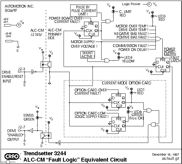
The following table lists all the internal conditions that will either prevent the ALC-CM drive from being enabled, or will disable the ALC-CM drive after being enabled. These conditions are represented as "Active Low" signals on the internal fault schematic. |
| Internal Signal Name | Function | Possible External Causes |
|---|---|---|
| MOTOR OVER
TEMP! Red LED behind J2 (between boards) |
Indicates loss of continuity between J3-6 and J3-7 | 1) Locked rotor on motor 2) Wiring harness open problem |
| DRIVE OVER TEMP! | Indicates that the ALC mounting plate temperature is above 55 degree C | 1) Locked rotor on motor 2) Excessive load duty cycle 3) Lost of customer supplied cooling |
| NEGATIVE BIAS
FAULT! Yellow LED behind J2 (between boards) |
Indicates loss of primary side logic supply voltage | 1) Low AC line 2) Brown-out of AC line during acceleration or heavy motor loading 3) Intermittent AC line connection |
| POSITIVE BIAS FAULT! | Indicates loss of primary side logic supply voltage | 1) Low AC line 2) Brown-out of AC line during acceleration or heavy motor loading 3) Intermittent AC line connection |
| POWER BOARD
OVER CURRENT! C limit |
Power board Pulse by Pulse current limit functions failed to regulate output current to a save level | 1) Phase to phase motor
short 2) Phase to frame motor short 3) High cable shield loss 4) Very low motor inductance 5) Current loop poorly tuned |
| MOTOR SUPPLY OVER VOLTAGE! | Primary Side Motor Supply is
at or above: 230 Vac Unit: ~ 440 VDC 115 Vac Unit: ~ 200 VDC |
1) External shunt resistor
not connected to J9 2) External Shunt resistor is improperly sized 3) Excessive AC line voltage |
| COMMUNICATION FAULT! | Invalid commutation state detected. Note: ALC-CM units manufactured after 8/1/96 no longer include this function. Newer units are self protecting, but do not respond to this condition by producing a latching fault. | 1) Improper J3 harness
shielding or design 2) Bad motor calibration, adjustment, or sensor placement 3) Incompatible motor transmitting element for desired cable length or application environment |
| POWER ON DELAY! | 150 mSec to 250 mSec low going pulse when AC line power is first applied. The ALC will continue to force a latching fault until this signal times out. | 1) Drive fails to reset and run because external control system attempts operation before ALC logic supplies have stabilized. |
| OPTION CARD
OVER CURRENT FAULT! LED1 |
Current mode option card current limit functions failed to regulate output current to a safe level | 1) Phase to phase motor
short 2) Phase to frame motor short 3) High cable shield loss 4) Very low motor inductance 5) Current loop poorly tuned |
| OPTION CARD
LOW LOGIC SUPPLY FAULT! LED6 |
Indicates loss of primary side logic supply voltage | 1) Low AC line 2) Brown-out of AC line during acceleration or heavy motor loading 3) Intermittent AC line connection |
| Submitted by Carl Vanmaarseveen on November 11, 1997 |