
Home | Contact Us | Submit Troubleshooting Info | Search | Help


    Output | Software Solutions | Proofing | Color, Screening and Calibration | Scanning | Digital Photography | Consumables | POS


AL-Ready Trendsetter VLF

Objectives: To position and lower the Trendsetter (involves removing the castors).

  1. Position the Trendsetter VLF in its approximate location.
    1. Using a measuring tape, check the minimum distance to the nearby walls or posts.
    2. Roll the machine into the correct position.
    3. Verify the distance on the floor layout diagram.
  2. Remove all seven side panels from the machine.
    This will give access to the engine, fan box and power box. Place the panels in a safe location.
  3. Remove all internal packing material, including the counterweight restraint strap.
  4. Open the electronics card cage and check that all circuit boards are properly seated.
  5. Install the table bumpers that were removed for shipping. The table bumpers for some Trendsetter VLFs rest on the front panels. For those panels, you must replace the panels after installing the bumpers. For other machines, the bumpers rest on the top frame.
  6. Set the coarse Trendsetter VLF height using the 3 adjustable feet.
    Lay on the floor, reach under the machine, and rotate each adjustable foot down two full turns from the fully 'up' position. Use the adjustable foot wrench as required.
  7. Position the 4 lifting jacks (#92-0084).
    1. Place the lifting bars (#56-3266) through the square holes in the engine casting.
    2. Check that the hose tray is up out of the way of the lifting bars.
    3. Slide the lifting jacks into the tube ends. Make sure the jacks go in all the way.
  8. Raise the Trendsetter VLF and remove the castors.
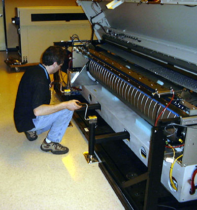
    1. Carefully raise the jacks until the bars are bearing against the top of the engine casting holes at all 4 points.
    2. Place a wood block under each corner of the Trendsetter VLF for safety.
    3. Raise the jacks, alternating between the 4 jacks so that the machine is kept level.

    4. WARNING! Do not let any of the lifting points get significantly higher or lower than the others, as this could twist the frame or cause instability.
    5. Stop lifting when the castors are off the ground and there is room to remove the castor screws.
    6. Check that the wood blocks are still positioned correctly under the corners of the machine.
    7. Remove the 4 screws holding each castor to the Trendsetter VLF frame.  Save the castors at the site in case the machine has to be moved again in the future.

      Using jacks to raise and lower the Trendsetter VLF

  1. Lower the Trendsetter VLF.
    1. Make sure that the power box and fan box pucks (pod feet) are fully up. If they are resting on the ground, raise the Trendsetter VLF using the jacks and rotate the adjustable feet down (1 full rotation = 7 mm height).
    2. Lower the jacks until the lifting bars are no longer touching the engine casting.
  2. Check that the engine is level.
    1. Place the spirit level along the casting under the drum and take a reading.
    2. Rotate it 90° and place it on a motor plate beside the drum. You may need to open the hood to place the level. Be careful of the p-door.
    3. To adjust the engine level:
      • Using the adjustable foot wrench, rotate the appropriate adjustable foot in the direction of least deflection
      • Recheck the engine level
  3. Adjust the power box and fan box pucks (pod feet).
    Rotate the pucks down by hand until they are just touching the ground, then rotate them down one more turn.

    WARNING! Do not lower the pucks further or the frame will twist.

  4. Remove the jacks and lifting bars.
    Store the lifting bars onsite for future use, usually in the back of the machine.
  5. Lower the hose tray to its lowest position.
  6. Check the shop air system pressure, using the air supply gauge (#92-0373A).
    See the Air Supply Qualification Procedure in Section 6.1 of the Trendsetter VLF AL site preparation .
  7. Install an air fitting onto the Trendsetter VLF.
    1. Check that the Autoloader shut-off valve, in the supply line after the regulator, is OFF.
    2. Connect the shop airline.
    3. Set the Trendsetter VLF internal pressure regulator in the fan box to 80 psi. You may need to remove an access panel.
    4. Replace the access panel if it was removed.

    Copyright © 2005 Creo Inc. All rights reserved. Confidential. Back to top.