Home | Contact Us | Submit Troubleshooting Info | Search | Help
Output | Software Solutions | Proofing | Color, Screening and Calibration | Scanning | Digital Photography | Consumables | POS
Home | Contact Us | Submit Troubleshooting Info | Search | Help
Output | Software Solutions | Proofing | Color, Screening and Calibration | Scanning | Digital Photography | Consumables | POS
 Inspect all delivered crates and boxes. These will normally be located
in the customer's loading dock area.
- Check that all the shipped crates have been received.
- Check that the toolkit crate is still locked.
- Check any shock watches on the outside of crates. They should be white, not red.
- Look for signs of damage from moisture, improper packing, tipping, dropping, stacking, etc. of crates, or any sign of mishandling.
Record any problems immediately on the Installation Report form and
report them to both Creo and the Delivery Company.
If space is tight, consider the best sequence in which to install the
components before starting to unpack the crates.Note: Do not clutter the workspace.
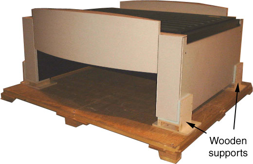
Unpack the conveyor first.Straight Conveyor
- Remove the crate top and sides.
Straight conveyor
- Remove the wooden supports.
- Have the forklift operator remove the conveyor from the crate. It can either be placed on the floor for rolling, or be moved by forklift directly to its permanent location.
- Leave the foam pad covering the plate deck in place. Small items from the other crates can be stored on it.
L-Conveyor
tbd
Rotating Conveyor
tbd
SCU only - Unpack the cassette cart (part of the SCU).
- Remove the crate top and one side only.
- Cut the tie straps holding the cart to the crate.
- Have the forklift operator remove the cart from the crate. It can either be placed on the floor for rolling, or be moved by forklift directly to its permanent location.
- Leave the foam pad covering the plate deck in place. Small items from the other crates can be stored on it.
MCU only - Unpack the MCU and cassettes.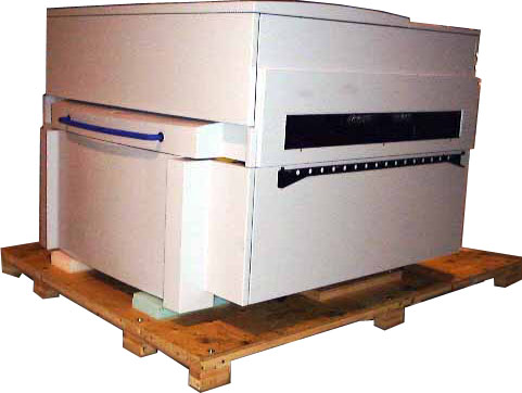 MCU crate
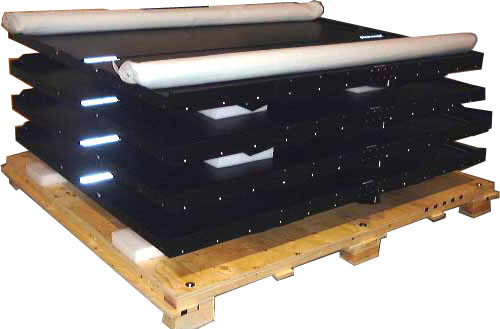 MCU cassettes crate
Unpack the Trendsetter VLF.
- Open the crate to allow access to the front and rear of the machine.
- Remove all packages from the crate and put most of them on the conveyor's foam pad or in a cassette (if ordered):
- adjustable foot wrench
- fasteners
- floor plate (SCU only)
- guard rail assemblies (2) including base plates and struts
- lifting bars
- picker with skins
- rear access guards (3 rear and 2 sides)
- track skins (3)
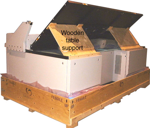
- Do not remove the temporary table supports yet. These supports can be removed once the TS has been put into its final position.
TVLF rendsetter crate
- Remove the front center panel and both rear panels.
- Raise the hose cage to gain access to the forklift rails.
WARNING! Moving the Trendsetter VLF by forklift when its front and rear panels are still on will damage the machine. Be careful not to damage the plastic cable channels directly under the forklift's arms.
- Have the forklift operator remove the Trendsetter VLF from the crate. Lift it carefully as one side is heavier than the other. The machine can either be placed on the floor for rolling on its castors, or be moved by forklift directly to its permanent location.
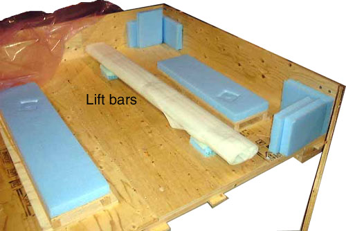
- Remove the lift bars from the bottom of the crate.
Lift bars location
Unpack the track.
- Remove the crate top, but do not remove the track from its crate.
- Discard any excess packing material.
- Lift the crate by hand onto dollies and roll it to its permanent location.
Note: Do not unpack the track until you are ready to install it.
Unpack the garage (part of the Single Cassette Unit).
- Remove the crate top and sides.
- Remove all packing material.
- Remove the temporary fasteners securing the garage plate to the bottom of the crate.
- Leaving the garage on the crate bottom, move it to its permanent location using a pallet jack.
Note: Do not take the garage off the crate bottom until you are ready to install it.
Unpack the Slipsheet Removal Unit.
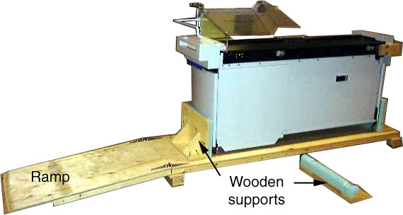 SSR crate
Unpack the workstation.Note: Do not unpack the workstation until you are ready to install it.
Unpack the imaging head.Note: Do not unpack the imaging head until you are ready to install it.
Unpack the Autoloader toolkit (#04-0018A).