|
Product |
|
Thermal 2 head |
|
Background |
|
Focus learn issues are often caused by problems with media handling and loading.
This procedure provides an easy method for determining if a focus learn problem is due to the way
the media is handled or loaded.
|
|
Errors |
|
[03529] System: Failure of the focus learn[01313] Focus: Focus error: Media out of range
|
|
What is the focus learn table? |
|
- At the beginning of a plot the TH2 head checks the profile of the plate during the first two swaths. This ensures that the autofocus system is able to track the plate. The focus learn table represents the commanded focus lens positions for each focus sample.
Focus sample: The following shows the commanded focus position (LPos).
Note: The number of samples will vary depending on the size of the plate.
0 |
-73.922 |
1 |
-74.022 |
2 |
-73.922 |
3 |
-73.621 |
... |
|
... |
|
288 |
-62.387 |
289 |
-62.688 |
290 |
-62.989 |
- If the profile of the plate cannot be tracked then the head will report the error
[03529] System: Failure of the focus learn.
- If everything is OK, then the plot will start. The head continues checking the profile of the plate for all the swaths in the plot, but it does not stop the plot if there are problems tracking the plate. If there are problems, the head reports the error
[01313] Focus: Focus error: Media out of range.
|
|
Procedure |
|
- Load a plate, preferably the same size and thickness of the plate that is failing. Alternately, you may use
a plate that has already failed on the focus learn.
- Increase the TH2 verbosity using the following commands:
›› redirect enable – communication with the thermal head is established›› vbs enable foc 7 – turn up the verbosity on the focus system›› redirect pass – communication with the MCE is established with TH2 feedback
- Plot an image to the plate. Use plot 5 on a negative plate or plot 12 on a positive plate. Using these
patterns the plate will not be exposed, so it can be re-used until a focus learn problem occurs.
- Repeat the plots until one fails focus learn.
- Generate a copy of the focus table using the following commands:
›› redirect enable – communication with the thermal head is established›› foc get table – this will make the head display the focus table as shown above.
The left column is the sample number and the right column is the lpos value. As the number becomes more negative, the lpos is moving away from the drum.
- In Excel, graph the results of the
foc get table command using the attached spreadsheet. You will get a result that looks like this:
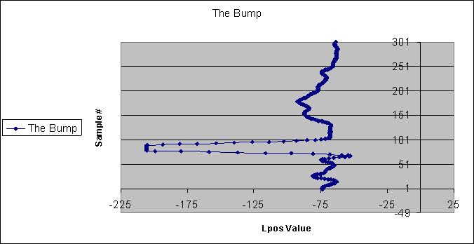
The spike in the graph indicates a bump on the media. This graph also indicates that the head is not installed in an
optimum position. Notice that lpos is never greater than -60. This leaves a focus travel of 140 microns. If the customer uses a single plate thickness, a position of 0 will allow a focus travel of 200 microns, which provides more room to move over any bumps.
This would be a better position because it would allow the focus actuator more range when moving over a bump.
- You can also determine the position on the drum where the focus learn failed. Look at the output until you see
the lines:
foc sample rate = 1896.722Hz
foc sample spacing = 2.476mm
Multiply the sample number by the foc sample spacing. This will indicate how far around the drum from the LEC/Head grippers the bump is positioned.
Important:
- This message may repeat several times before the plot starts. Always use the final set of numbers before the plot.
- Your values for
foc sample rate, foc sample spacing, and the number of samples may be different. These are just examples.
- To determine how far the bump goes into the plate from the edge, you could move the position of the plot using the command
›› plot shift 100 (This will move the plot over by 100mm or approximately 4 inches.
You should try this with various values for a shift.) When the plot completes, look for the following information:
FOC: MAE = 148 Max Lpos = -42.728 Min Lpos = -196.489 Mean Lpos = -60.281
Note that the bump still exists, but the autofocus system was able to compensate for the bump.
- The final step is to make a plot with the focus system fixed at a single point for the media that you are using:
›› set hdm 1 fmode 1 or ›› th2 set med 0 focusmode 1›› plot 22
This will produce a plate with a hotspot in the area of the bump. This can be helpful in determining what is causing the
bump during loading. Remember that the focus range is very small and you may not be able to detect a plate loading
problem by visual inspection.
- When you are finished:
- Return the focus mode to the original (correct) setting that you changed in step 9.
- Turn off the TH2 verbosity using the commands:
›› redirect enable
›› vbs disable all
›› redirect disable
Important: Failing to turn off the verbosity can cause connectivity problems, particularly with Brisque workflow.
|
|
See also |
|
- Bumps in the plate may be caused by a problem with the plate drop. See "Adjust the picker plate drop (step 12, TS NEWS preventative maintenance)'
- Troubleshooting TH2 focus errors
|
|
Technical contact |
|
Doug Jeffery |
Submitted by |
|
Doug Jeffery
|
Date submitted |
|
16 Jun 2004 |

