Requirements |
|
List any parts, tools, jigs, checklists, documents, software patches, and so on that the user will need to complete the procedure. (In the case of “soft” items like documents, include links to them.) |
Procedure |
|
Adjusting Subscan and Mainscan Shift
- In Service Shell, select the Device Monitor applet, and then select MCE from the Device Tree.
- Type the command
gc
to display a table showing all the current gc parameters for the master
and slave thermal heads. Take note of the current mshift and sshift
values for both thermal heads.
- Load two thermal plates into the TSC News device with command:
load m <xxx> s <yyy> ms 2
(xxx = mainscan dimension in mm; yyy = subscan dimension in mm)
- Enter command:
plot 100
- Process the plates.
- Use a pen to mark which plate was imaged by the master thermal head and which was imaged by the slave.
- For each plate, with the leading edge towards you, measure the distance between the crosshair in the lower left corner and the bottom edge (leading
edge) of the plate. This mainscan distance should be 25.4 mm (1 inch) ±0.5 mm from the leading edge of the plate.
- For each plate, with the leading edge towards you, measure the distance between the crosshair in the lower left corner and the left (home side) edge
of the plate. This subscan distance should be 25.4 mm (1 inch) ±0.5 mm from the left edge of the plate.
- If necessary, adjust the mainscan shift (gc mshift) and subcan shift (gc sshift) parameters for the master head.
Increasing the gc mshift value will move the cross hair upwards on the plate by the number of microns added. Increasing the gc sshift value
will move the cross hair to the right by the number of microns added.
The commands to change these values for the master head are as follows:
set gc mshift 1 <new value>
set gc sshift 1 <new value>
- If necessary, adjust the mainscan shift (gc mshift) and subscan shift (gc sshift) parameters for the slave head.
The commands to change these values for the slave head are as follows:
set gc mshift 2 <new value>

set gc sshift 2 <new value>
- Load two new plates and repeat steps 4 to 8 to confirm that the cross hairs are now in the correct positions.
- If they are not, repeat steps 9 to 11.
Note: If the cross hairs tend to move 1 or 2 mm in the subscan direction (left to right) over time or from plate
to plate, this could a result of changes in the surface reflectivity of the plate.
Surface reflectivity may change if the plate is old, or exposed, or fogged. In this case, use new plates. Surface reflectivity may
also vary from batch to batch from thermal plates. Sometimes, the emulsion is damaged 10 to 15 mm up from the leading edge of the
plate, causing changes in surface reflectivity. In these cases, contact the plate manufacturer.
To help diagnose variability in surface reflectivity from batch to batch of plates, use the foc cal reflect command, as described in the “Positioning the Headâ€? procedure. Be aware that the focus
laser will expose the plate and cause the output value to change over time. Either load new plates or move the drum or carriage so
that the focus laser is over fresh emulsion.
Adjusting Head Spacing
- Type the command:
gc
Take note of the current values for the mshiftslave and headspacing
parameters.
- To make it easier to see the stitch line when you image a test plot,
temporarily subtract 84.8 microns from the mainscan shift value currently
being used for the slave head.
Type the command:
set gc mshiftslave <current value - 84.8>
- Load a panorama plate into the device with the command:
load m <xxx> s <yyy> ms 1
(xxx = mainscan dimension in mm; yyy = subscan dimension in mm)
- Type the command:
plot 22
(2 x 2 pixel checkerboard)
- Process the plate and mark the leading edge with a pen.
Note: Ignore any banding that appears on the plate. This is normal for
this test pattern when imaged by 1200 dpi thermal heads. It does not
appear under normal imaging conditions, with customer TIFF files.
- With the leading edge towards you, use a 100 power microscope to examine
the very bottom of the stitch line. Each square represents 42.4 microns.
Details...
Note:
Typical 100 power microscopes invert the image, so when viewing
the stitch line under a microscope with the leading edge of the
plate towards you, keep in mind that the plot to the left of the
stitch line was imaged by the slave head, while the plot to the
right was imaged by the master head.
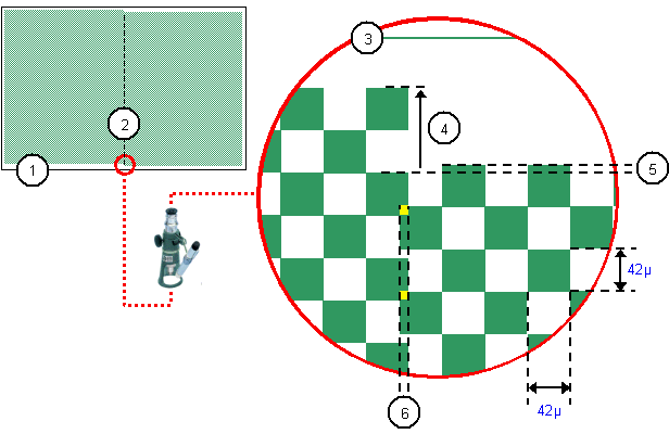
Stitch Line As Viewed Thorough Typical 100X Microscope
(after 84.8µ temporarily subtracted from mshiftslave value)
 |
Leading edge of plate |
 |
Stitch line on plate |
 |
Leading edge of plate as seen through
microscope |
 |
Distance (84.8µ) that squares imaged by
slave head were shifted towards the leading edge of the plate in
step 2 |
 |
Error in mainscan direction.
- To move squares on slave head side of the stitch line away
from leading edge of plate, increase value of
mshiftslave
parameter.
- To move squares on slave head side of the stitch towards
leading edge of plate, decrease value of
mshiftslave
parameter.
|
 |
Error in subscan direction.
- If squares overlap along the stitch line (as shown) decrease
value of
headspacing parameter to compensate.
- If there is a gap between squares along the stitch line,
increase value of
headspacing parameter to
compensate.
|
- Adjust the slave head offset parameter so that the first row of squares on
the master head side of the stitch line is aligned with the third row of
squares on the slave head side. Enter command:
set gc mshiftslave <new value>
Increase gc mshiftslave to move squares imaged by
the slave head away from the leading edge of the plate.
Decrease gc mshiftslave to move these squares towards the
leading edge.
Note...:
| |
Depending on the subscan
dimension of the plate, the 2 x 2 pixel checkerboard patterns imaged
by the master and slave heads may not always line up so that one row
ends with a solid square and the other begins with a space or vice
versa. Sometimes, the patterns will line up so that two spaces and
two squares meet each other on either side of the stitch line. |
| |
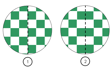 |
|
|
Example 1: For every row that ends with
a solid square, the corresponding row begins with a space, and vice
versa. |
|
|
Example 2: For every row that ends with
a solid square, the corresponding row begins with a solid square,
and for every row that ends with a space, the corresponding row
begins with a space. |
| |
|
- Adjust the headspacing parameter so that the squares just touch each other
in the subscan direction (left to right). Enter command:
set gc headspacing <new value>
(Increase gc headspacing to close a gap along the
stitch line.
Decrease gc headspacing to reduce an overlap along the
stitch line.
- Load another panorama plate and repeat steps 4 to 6 to confirm that the
first row of squares on the master head side of the stitch line is aligned
with the third row of squares on the slave head side, and that there is no
gap or overlap of squares along the stitch line.
Details...
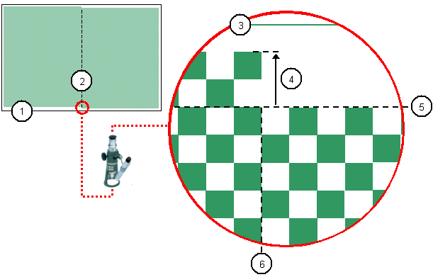
Stitch Line As Viewed Thorough Typical 100X Microscope
(after first stage of geometric correction)
| |
Leading edge of plate |
|
Stitch line on plate |
|
Leading edge of plate as seen through
microscope |
|
Distance (84.8µ) that squares imaged by
slave head were shifted towards the leading edge of the plate in
step 2 |
|
1st row of squares on master head side
of stitch line aligned with 3rd row of squares on slave head side |
|
Stitch line as seen through microscope |
| |
|
- If the first row of squares on the master head side of the stitch line is
not aligned perfectly with the third row of squares on the slave head side,
or if there is a gap or overlap of squares along the stitch line, repeat
steps 7 to 9.
- Using a microscope, inspect the squares on either side of the stitch line
at the other edge (trailing edge) of the plate to ensure that they line up
perfectly in the mainscan direction. They should line up perfectly,
but in the unlikely event that they don't, you may have to adjust the
mscale
(mainscan scale) parameter to compensate.
Details...
- Determine the distance in microns by which the image produced by the
slave head needs to be scaled up or down in the mainscan direction in
order to line up with that produced by the master head.
- Enter command
set gc mscale 2 <value>
where <value> is the increase or decrease in parts per
million.
To calculate this value in parts per million:
(D ÷ H) x 1000
where D = distance in microns by which slave head image needs to
be scaled up or down, and
H = height (dimension in mainscan direction) of the image in mm
- Add the 84.8 microns you subtracted from the mainscan shift value in step 2
back onto the value now being used for the slave head.
Enter command:
set gc mshiftslave <current value + 84.8>
- Load another panorama plate into the device and image it with
plot 22 (as described in steps 3 & 4, above). Process the plate and
verify that subscan shift, mainscan shift, and head spacing are set up
correctly. (The stitch line should be very difficult to detect, even under a
microscope.)
|

