Procedure |
|
Removing & Replacing the LECs
- If necessary, power off the device and, if applicable, separate it from the loader.
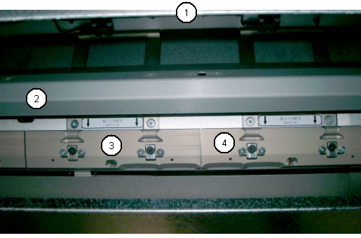
- From the loading slot at the rear of the device, rotate the drum until the LECs are accessible, toward you relative to the load ramp. You may have to
lift the LEC backbone, the roller backbone, and the TEC backbone to rotate the LECs to this position.
 |
TEC backbone (partially obscured by
sheet metal panel at upper rear of device) |
 |
Load Ramp |
 |
LEC Assembly (500-01350A,
#2 & 4 from home side) |
 |
LEC Assembly (500-01351A,
#1 & 3 from home side) |
| |
|
- Use a 3 mm hex key to loosen the M3 screws attaching the center of
the LEC rockers to the drum.
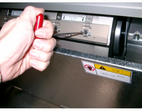
- Hold the LEC assembly against the drum with one hand, and with the other
hand, remove the screws you loosened in the previous step.
- Carefully lift the LEC assembly away from the drum, taking care not to
drop the springs protruding from the drum.
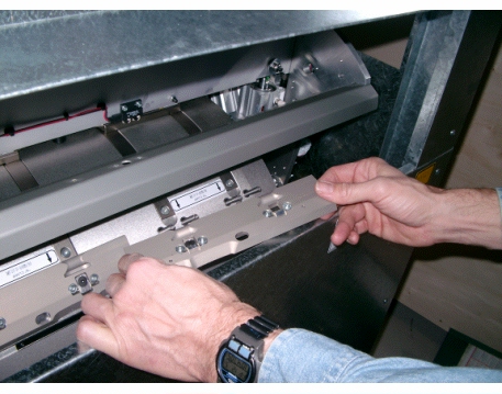
- Position the new LEC assembly against the drum, with the springs
compressed and the M3 screw holes aligned against the tapped holes in the
drum.
Note: Take care to ensure that you are using the correct LEC assembly
for the location on the drum. Assembly 500-01351A is used for
positions 1 & 3 (starting from the home side of the drum), and
assembly 500-01350A is used for positions 2 & 4 from the home
side.
- Insert the two M3 screws through the holes in the LEC assembly into the
drum. After you get both screws started, tighten one a few turns, and then
the other, until the screws are fully tightened.
- With the heel of your hand, push the top of the LEC clamp assembly toward
the drum to ensure that the springs are correctly aligned. The top of the
clamp should rest flat against the drum when pressed down.
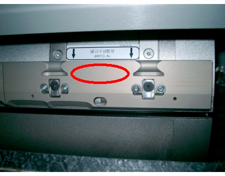
Press against the area highlighted in the photo with the heel of your
hand.
- Repeat steps 3 to 8 for any remaining LEC assemblies that need to be
replaced.
- Power up the device and load a plate to verify that the new LEC assemblies have been installed
correctly.
|

