Networking Devices - LANplex
2500 Installation
LANplex2500
The LANplex2500
manufactured by the 3Com Corporation, is a SNMP-managed
(Simple Network Management Protocol) FDDI to Ethernet
switching hub. It provides as a basic unit, eight SW
(switched) 10Base-T Ethernet ports, and one high speed
FDDI Dual Attach port, these can be expanded to a maximum
configuration of sixteen SW (switched) 10Base-T Ethernet
ports, and two high speed FDDI Dual Attach ports. The
LANplex 2500 can be used for connecting a Ripro Server
with a Ripro FDDI Board (#501R44011), SciNet FDDI
stations (Whisper with FDDI board) up to sixteen Ethernet
segments. In the future it will also connect a Ripro
Server which has a SciNet FDDI board.
Each Ethernet segment
can be connected to a high end workstation in order to
provide the station with full Ethernet bandwith
(10Mbit/sec) or can be connected to a workgroup hub
(TP/8i) that will share the Ethernet bandwidth between
the workgroup stations. Ethernet clients can be SciNet
clients (PTOP) and/or standard protocol clients
(AppleTalk, TCP/IP, IPX, etc.)
For high-traffic local
LANs, the LP2500 switching hub improves local network
throughput and client/server performance, easily and
affordably. The two high-speed fiber FDDI ports connect
to file servers to provide 100Mb/sec (Mbit per second)
connectivity or connect to high end workstations with an
FDDI interface or connect as a network backbone.
LinkBuilder TP/8i
The LinkBuilder TP/8i
is a stand-alone Ethernet repeater with eight ports for
connection to 10Base-T networks. The LinkBuilder TP/8i is
used in conjunction with the LANplex2500 as a workgroup
hub, to expand an existing network, which can connect up
to seven workstations and also connects to a switched
Ethernet port of the LANplex2500.
Logistics
The following kits are
used when installing the LP2500 with an FDDI DA port in
the Ripro Server:
| Item
# |
Catalog
Name |
Catalog
No. |
| 1 |
SW Hub, LP2500 (one PS) |
501R44134 |
| 2 |
SW Hub, LP2500 (two PS) |
501R44135 |
| 3 |
Ethernet module, 8 port for LP2500 |
501R44136 |
| 4 |
FDDI Media MIC Module for LP2500 |
501R44137 |
| 5 |
LinkBuilder TP/8i-Managed Hub. |
501R44160 |
Note:
Both LP2500 units are upgradable to sixteen Ethernet
ports and two FDDI Fiber Dual Attach ports using the
modules (item# 3, 4).
Item# 2 has an extra (redundant ) power supply.
These
installation instructions deal only with the necessary
information to install and activate the unit and connect
to Scitex Systems. For further details refer to the
following booklet which is supplied by the manufacturer
together with each unit:
- LANplex2500 Getting Started.
- LinkBuilder TP/8i User Guide, 3C16181.
Locating the LP2500 and TP/8i
- Can be either wall mounted,
free standing or mounted in standard 19-inch rack
equipment. Scitex requires installing the
communication devices only in a 19-inch rack.
- Ensure that there is adequate
access for all maintenance purposes and free air
flow.
- Make sure that the cabling is
away from all sources of electrical noises, power
lines and lighting fixtures.
Installing
an Option Module
The LP2500 is supplied with an
Ethernet option module and an FDDI module, these are not
installed.
To install these modules and
additional modules refer to LANplex 2500 Getting Started,
Chapter 3 Installing Option Modules.
The LP2500 runs diagnostics
software at power up. The system processor LEDs indicate
whether the LP2500 is functioning properly.
| System
Diagnostic LEDs |
| LED |
LED
color |
Indicates... |
| Power |
Green |
System
powered on |
| Run |
|
System
operating |
| Run |
Green |
System
running diagnostics |
| Processor |
Yellow |
System
processor has failed at power up |
| Power
|
Yellow |
For
redundant power supplies only. PS out of
specification |
| Fan |
Yellow |
For
redundant power supplies only. Fan slowed or shut
down |
| Config
|
Yellow |
Hardware/Software
revision mismatch |
| Inserted |
Green |
PCMCIA
card inserted |
When diagnostics run on a
particular module the Port Status LEDs are lit
(see Figure 1. LANplex2500 Back
Panel slot 3 and/or slot 4 below).
| LED |
LED
color |
Indicates... |
| Port
Status - Error |
Yellow |
System
running diagnostics |
| Port
Status - Error |
Yellow (after completion of diags) |
Port
not operational |
| LED |
LED
color |
Indicates... |
| Port
Status - Active |
Green |
System
operating for connected ports |
| Board
Error |
Yellow |
Module
failed diagnostic test |
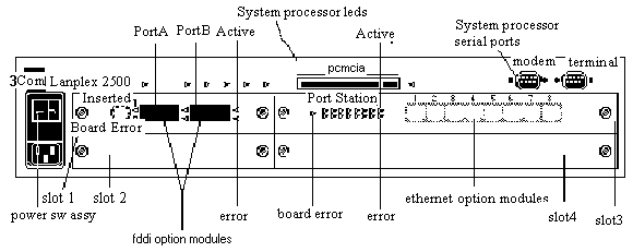
Figure 1. LANplex2500 Back Panel
There are eight Ethernet ports
(1-8) with shielded RJ45 data sockets suitable for direct
connection to a workstation using twisted pair cable
(Scitex recommends only using infrastructure cable 4x2W
(wall cable) and patch cable ,both must comply with
category 5 standard), or connection to a number of
stations connected to workgroup hub (TP/8i). These ports
are implemented as MDI-X (media dependant interface
crossover) to enable the direct connection with a
straight through cable.
Connecting
to LinkBuilder TP/8i
- To connect the LinkBuilder
TP/8i to a LP2500 Switching Hub or to
anotherLinkBuilder TP/8i use port 8 with the MDI
switch on the LinkBuilder TP/8i pushed-in.
- Connect the one side (male) of
the RJ45 patch cable to a port of the LP2500
Switching Hub and the other side of the cable to
port number 8 of the LinkBuilder TP/8i.
- To connect the LinkBuilder
TP/8i to a workstation use the ports with the
RJ45 (male) connector to connect directly to the
workstation (through a patch panel located in the
communications rack).
Note: The MDI (Media
Dependent Interface) controls the operation of port 8.
Refer to Installing the TP/8i, MDI Switch.
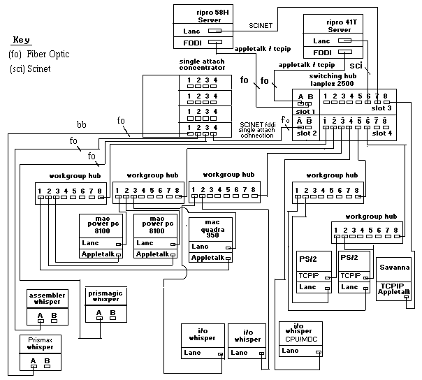
Figure
2. Connecting up the LP2500 and TP/8i
Connecting
to FDDI
Each LP2500 Switching Hub can
support:
- Two FDDI SA connections or one
FDDI DA connection, by installing one FDDI board.
- Four FDDI SA connections or
two FDDI DA connection, by installing two FDDI
boards.
The Serial Port provides RS-232
connection to a local terminal, modem or workstation
(laptop running terminal emulation program).
- Use the RS-232 cable
(#504G34023 or #504G34023A) to connect the serial
port on the LP2500 to the terminal serial port on
your laptop (instead of your mouse).
- Do not power ON the LP2500.
- Power ON your laptop and at
the prompt(C:>) type win and press Enter.
- When the Windows main screen
appears press ALT+W.
- Use the arrow keys to select
Accessories from the pull-down menu and press
Enter.
- Use the arrow keys to select
Terminal from the items in the Accessories group
and press Enter.
- Press ALT+S to select Settings
from the menu bar and use the arrow keys to
select Terminal Emulation and press Enter.
- Select VT100 and press
Enter.
Terminal Emulation:
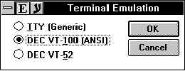
- Press ALT+S to select Settings
from the menu bar and use the arrow keys to
select Communication and press Enter.
The Communications window appears.
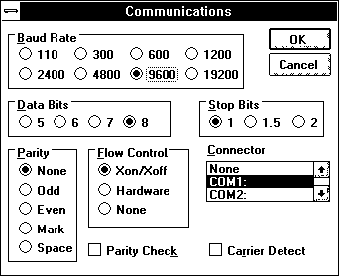
- Use the arrow keys to navigate
within a section and use the TAB key to move from
section to section.
The following settings must be completed:
| Baud Rate |
9600 |
| Data bits |
8 |
| Stop bits |
2 |
| Parity |
None |
| Flow Control |
Xon/Xoff |
| Connector |
com1 |
- When you have completed the
settings press Enter.
TURN ON THE LP 2500 !
- Power on the LP2500
Accessing the Administration
console
- At the Terminal screen press
Enter twice.
- At the Administration console
prompt type administer and press Enter.
- At the password prompt press
Enter.
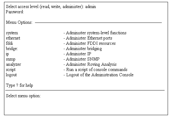
The Administration Console main menu appears.
The following is the recommended
structure for Scitex IP addresses:
| Station/Unit |
Recommended Address |
First
Ethernet Communication board
(ent0) on Ripro Server (Ripro1) |
192.9.100.X
(X is 1-20) |
Second
Ethernet Communication board
(ent1) on Ripro Server (Ripro1) |
192.9.110.X
(X is 1-20) |
Third
Ethernet Communication board
(ent2) on Ripro Server (Ripro1) |
192.9.120.X
(X is 1-20) |
Fourth
Ethernet Communication board
(ent3) on Ripro Server (Ripro1) |
192.9.130.X
(X is 1-20) |
| FDDI
Adapter (fi0) on Ripro Server |
192.9.150.X
(X is 1-20) |
| Mac |
192.9.Y.[21-74] |
| PS/2 |
192.9.Y.[75-99] |
| Sun |
192.9.Y.[100-119] |
| Whisper
|
192.9.Y.[120-149] |
Communication
units
(hubs, routers, switching hubs etc.) |
192.9.Y.[200-254] |
Examples
- Y-is determined by
the Network communication board on the particular
server. 192.9.110.25- is a Mac connected to the
Second Ethernet board on Ripro1.
- 192.9.150.125- is a
Whisper connected to FDDI through the Switching
Hub.
- The first Mac
connected to ent0 will have an address of
192.9.100.21.
- The first PS/2*
connected to the Ripro Server via the FDDI
adapter and Switching Hub will have an IP address
of 192.9.150.75.
- The first Whisper
connected to ent1 will have an address of
192.9.110.120
Setting Up the IP Address
- At the Administration Console
main menu type ip.
- At the ip menu type interface.
- At the interface menu type
define.
- Enter the IP address of the
interface.
| IP
Address |
192.9.150.200-[recommended
Scitex IP range of addresses for communication
units is 200-254] |
| Network
Mask |
255.255.255.0 |
| Gateway
Address |
If
there are no routers on the network, the Gateway
address is not needed. |
| Broadcast
|
<
ENTER > |
| Enter
Port |
All
--> < ENTER > |
- Press q to quit.
Note: Where the IP
addresses are set according to Scitex defaults use the
above example. Where the IP addresses are set according
to the site network configurations, use the site IP
addresses for the LP2500 configuration. The site
administrator should provide you the IP address, Network
Mask and Gateway Address.
LP2500
Network Configurations
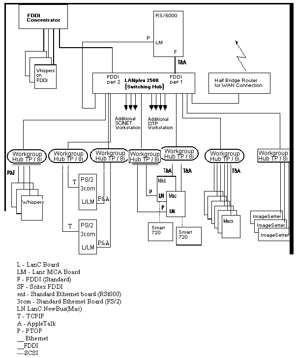
The following diagrams illustrate
the different configurations using the LP2500.
Figure
5. Typical Network with a Ripro Server and LP2500
LP2500
Optional Configurations
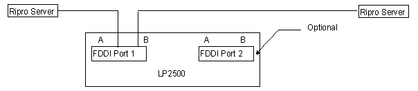
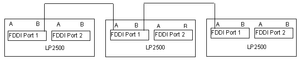
Each FDDI DA module can support the
following configurations:
LP2500
with a single FDDI DA module and Ripro Servers
Cascade
of LP2500 systems with SA connection
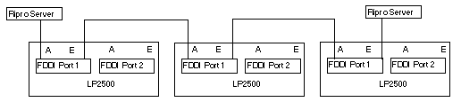
Combination
cascade of LP2500 systems with SA connection and Ripro
Servers
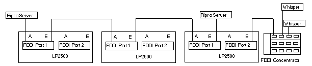
Combination
cascade of LP2500 systems with SA connection , Ripro
Servers and FDDI Single Attach Concentrator
You can communicate with the LP2500
over the network using any Telnet facility that emulates
a VT100 terminal (you can use any Mac on the network
supporting this mode or any UNIX station).
- To open a Telnet session type
telnet 192.9.150.200 (LP2500 IP address).
- Type admin (for access level)
and type Enter (password).
When the connection is established the following main menu screen
appears.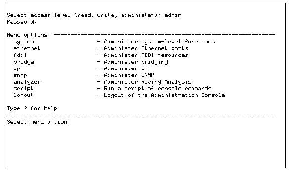
Panels
and LEDs
Front Panel
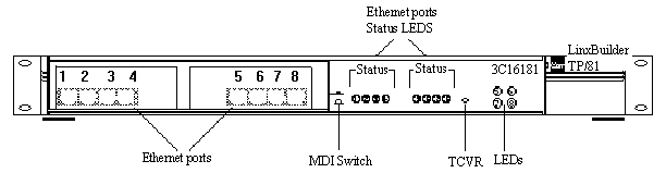
LinkBuilder
TP/8i Front Panel
Ethernet Ports
Shielded RJ45 data sockets.
MDI Switch
Controls operation of port 8.
| MDI |
In |
In
this position you can connect port 8 to any
internal cross-over port on another 10Base-T
unit. |
| MDI |
Out |
In
this position you can connect port 8 to a
workstation or any other Data Terminal Equipment
(DTE). |
Status LEDs
Display partiition state of a port, whether there is a
Link Pulse on segment connected to port. The Link Pulse
signal verifies if there is a link to the port.
| Green |
Link
Pulse is being received-segment is operational |
| Red |
Link
Pulse is being received-port is partitioned from
network. |
| Off |
Link
Pulse is not being received |
TCVR
TCVR LED will light red if Transceiver
Module port has partitioned
LEDS
| Packet
LED (5) |
Packet
LED when a packet received on
one of the Ethernet ports. If LED does not flash,
no packets are being received. |
| Power
LED (6) |
Green for normal operation.
Refer to User guide in event that LED not lit. |
| Collision
LED (7) |
when a packet collision
detected on a segement connected to one of the 8
Ethernet ports. |
| MGMT
LED (8) |
Shows
status of hub management software.
Green - normal operation.
- Management software
downloaded to hub.
Red - Fault with hub. |
Rear
Panel
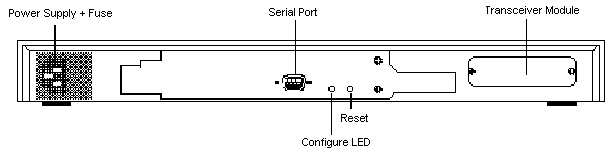
LinkBuilder
TP/8i Back Panel
| Power
Supply and Fuse |
Hub
automatically adjusts to supply voltage. Fuse
suitable both 110 AC and 220-240AC. |
| Ethernet
Address |
Mac
address of Hub. Supplied by manufacturer. |
| Serial
Port |
For
connecting local terminal for configuration and
management of Hub. |
| Configure
LED |
Yellow when on, operates in conjunction
with Reset Button. |
| Reset
Button |
Used
for restarting hub and entering Software Upgrade
Configuration Utility (downloading new management
software). |
| Transceiver
Module Slot |
For installing a
3Com Transceiver Module providing a ninth port. |
Wake-Up
- Connect your laptop to the
serial port of the unit you are configuring
- At the terminal screen press
Enter, twice and type go.
After the wake-up procedure is performed the
following screen opens:
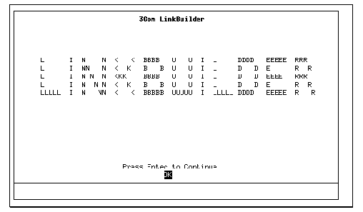
- Press Enter to continue.
Logon
- To use the management
interface enter your user name (type secure) and
password (type secure).
- Refer to LinkBuilder TP/8i
User Guide, 3C16181, Chapter 3 Using the VT100
Management Interface, to determine access levels
and security for default users.
- After you logon press Enter.
You can now access the Main Menu.
Setting
IP Address
- At the Main Menu screen select
Setup.
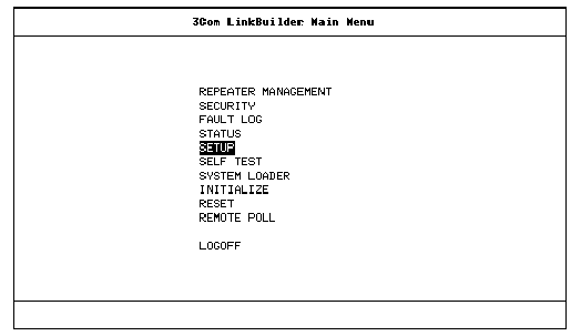
The setup screen is used to configure IP
parameters for the hub.
- Fill in the parameters for the
IP address, Subnet Mask and Default Router (if
there is one) according to your site IP
addressing or Scitex defaults if no site
addressing exists. (Refer to IP
Addressing).
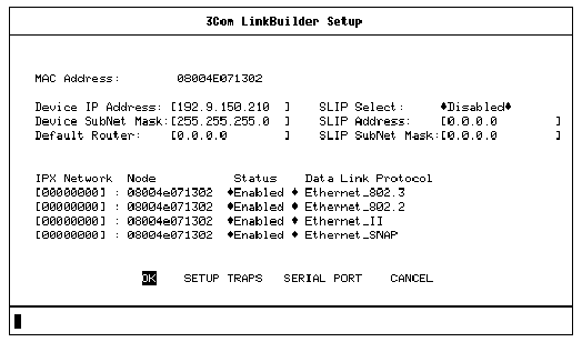
- After you complete filling in
the IP address parameters, press Enter (select
OK).
- Press Enter twice to return to
the Main Menu and then logoff.
For further information refer
to:
LinkBuilder TP/8i User Guide, 3C16181, Chapter 3 Using
the VT100 - Management Interface.
SWITCHING
HUB LP2500(1PS)
SCN:501R44134
| Scitex
Part No. |
D
e s c r i p t i o n |
| 138F00029 |
FDDI
CABLE ASSY L=30M DUALAN |
| 605A30124
|
LP2500
8PORT 10BIT/RJ-45 ETH.M |
| 605A30126 |
LP2500
FDDI DAS MIC FIBER MOD. |
| 605A30130 |
LANPLEX
2500CHASSIS 1P.SUPPLAY |
SWITCHING HUB LP2500(2PS)
SCN:501R44135
| Scitex
Part No. |
D
e s c r i p t i o n |
| 138F00029 |
FDDI CABLE ASSY
L=30M DUALAN |
| 605A30124 |
LP2500 8PORT
10BIT/RJ-45 ETH.M |
| 605A30126 |
LP2500 FDDI DAS
MIC FIBER MOD. |
| 605A30132 |
LANPLEX
2500CHASSIS 2P.SUPPLAY |
ETHERNET MOD.&PORT FOR LP2500
SCN:501R44136
| Scitex
Part No. |
D
e s c r i p t i o n |
| 605A30124 |
LP2500 8PORT
10BIT/RJ-45 ETH.M |
FDDI FIBER MIC MOD.FOR LP2500
SCN:501R44137
| Scitex
Part No. |
D
e s c r i p t i o n |
| 138F00029 |
FDDI CABLE ASSY
L=30M DUALAN |
| 605A30126 |
LP2500 FDDI DAS
MIC FIBER MOD. |
LINKBUILDER TP8/I-MANAGED HUB.
SCN:501R44160
| Scitex
Part No. |
D
e s c r i p t i o n |
| 605A30128 |
LINKBUIDER TP/8I
MANAG.ETH.HUB |
|

