Home | Contact Us | Submit Troubleshooting Info | Search | Help
Output | Software Solutions | Proofing | Color, Screening and Calibration | Scanning | Digital Photography | Consumables | POS
Home | Contact Us | Submit Troubleshooting Info | Search | Help
Output | Software Solutions | Proofing | Color, Screening and Calibration | Scanning | Digital Photography | Consumables | POS
Linkswitch 1200 Installation Guide
General DescriptionThe LS1200 (LinkSwitch 1200), manufactured by the 3Com Corporation, is a SNMP-managed (Simple Network Management Protocol) FDDI to Ethernet switching hub. It provides as a basic unit, six SW (switched) 10Base-T Ethernet ports, and one high speed FDDI Single or Dual Attach port. The LS1200 can be used for connecting a Ripro Server with a Ripro FDDI Board (501R44011) and/or SciNet FDDI stations (Whisper with FDDI board) to six Ethernet segments. Each Ethernet segment can be connected to a high end workstation in order to provide the station with full Ethernet bandwith (10Mbit/sec) or can be connected to a workgroup hub that will share the Ethernet bandwith between the workgroup stations. Ethernet clients can be SciNet clients (PTOP) and/or standard protocol clients (AppleTalk, TCP/IP, IPX, etc.) For high-traffic local LANs, the LS1200 switching hub improves local network throughput and client/server performance, easily and affordably. The high-speed fiber FDDI port connects to a file server to provide 100Mb/sec (Mbit per second) connectivity (an optional module adds a dual attached FDDI connection Benefits
LS1200 weaknesses
LogisticsThe following kits are used when installing the LS1200 with an FDDI port in the Ripro Server:
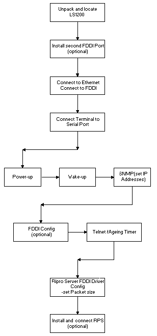
InstallationInstallation Flow Chart |
| LED color | Indicates... |
| Green | Normal function |
| Power On Self Test | |
| Red | That a fault has been detected |
| No LED | The LS1200 is not functioning |
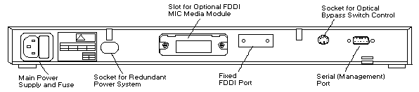
In order to support a Dual Attached connection or a second Single Attached connection, a second FDDI port module can be fitted to the LS1200.
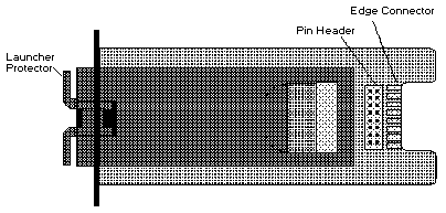
The FDDI MIC Media Module can transmit (Tx) and receive (Rx) FDDI 100 Mbit/sec traffic over multi-mode Fiber Optic cable.
LS1200
Rear Panel:
Connecting to the FDDI Network
1. Remove launcher -protecting device from the MIC connector.
2. Push the MIC connector (from the server) firmly into the MIC Media Module connector on the LS1200.
3. Power ON the LS1200.
NOTE: For configurations involving more than one
Ripro server and/or LS1200 refer to LS1200 Network Configurations
FDDI
MIC Media Module:
FDDI Status LEDs
There are three rows of two LED indicators to display the status of the FDDI ring and ports.
FDDI Ring
The upper row of the FDDI LEDs represents the state of the ring. The left Led is a bi-color (red/green) and the right LED is only yellow.
| Left LED | Right LED | Condition |
| Off | Off | Power up.FDDI ring not enabled. |
| Red | Off | Fault. FDDI ring not enabled. |
| Green | Yellow | FDDI ring active |
| Off | Yellow | Internal FDDI ring active-but no external FDDI ring. |
Optional Port LEDs
Middle row of LEDS indicates status of optional FDDI port. If this port is not installed the LEDs are always Off. If installed they indicate as for the fixed port.
Fixed Port LEDs
Bottom row of LEDs. The left LED is a bi-color (red/green) and the right LED is only yellow.
| Left LED | Right LED | Condition |
| Off | Off | Port disabled. |
| Red | Off | Fault-path test fail, or trace in progress. |
| Green | Yellow | Port has active FDDI connection. |
| Off | Yellow | IPort ready for FDDI connection. |
Troubleshooting
If the FDDI Ring is not active after the LS1200 powers up, check the following:
There are six Ethernet ports (1-6) with shielded RJ45 data sockets suitable for direct connection to a workstation using normal twisted pair cable, or connection to a number of stations via a HUB in a star configuration.
Ethernet Status LEDS
There are three rows of six LEDs on the front panel that indicate the status of the Ethernet ports.
LS1200
Front Panel

Link Status LEDs
The top row of LEDS indicates whether the port has a properly functioning link. The LEDs are bi-color (red/green).
| Color | Indicates that... |
| Green | The port is enabled and Link Pulse signal being received |
| Red | Loop detected, port inactivated |
| Off | The port disabled or no Pulse Link signal being received. |
Rx Leds
Middle row of LEDS indicates when packets are received at enabled ports. Each enabled port flashes yellow when packet received.
Tx LEDs
Bottom row of LEDS indicates when packets are transmitted at enabled ports. Each enabled port flashes yellow when a packet is transmitted.
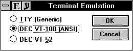
The Serial Port provides RS-232 connection to a local terminal, modem or workstation (laptop running terminal emulation program).
Terminal Emulation:
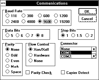
| Baud Rate: | 9600 |
| Data bits: | 8 |
| Stop bits: | 2 |
| Parity: | None |
| Flow Control: | XonXoff |
| Connector: | com1 |
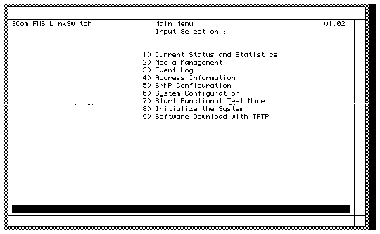
Wake-up
After setting the local serial connection settings you can perform the wake-up procedure.
The following is the recommended structure for Scitex IP addresses:
| Station/Unit | Recommended Address |
| First
Ethernet Communication board (ent0) on Ripro Server (Ripro1) |
192.9.100.X (X is 1-20) |
| Second
Ethernet Communication board (ent1) on Ripro Server (Ripro1) |
192.9.110.X (X is 1-20) |
| Third
Ethernet Communication board (ent2) on Ripro Server (Ripro1) |
192.9.120.X (X is 1-20) |
| Fourth
Ethernet Communication board (ent3) on Ripro Server (Ripro1) |
192.9.130.X (X is 1-20) |
| FDDI Adapter (fi0) on Ripro Server | 192.9.150.X (X is 1-20) |
| Mac | 192.9.Y.[21-74] |
| PS/2 | 192.9.Y.[75-99] |
| Sun | 192.9.Y.[100-119] |
| Whisper | 192.9.Y.[120-149] |
| Communication
units (hubs, routers, switching hubs etc.) |
192.9.Y.[200-254] |
Examples
SNMP Configuration
Use this option to set the LS1200 IP address.
| IP Address | 102.9.150.200-[recommended Scitex IP range of addresses for communication units is 200-254 |
| Network Mask | 255.255.255.0 |
| Gateway Address | If there are no routers on the network, the Gateway address is not needed. |
NOTE: Where the IP addresses are set according to Scitex defaults use the above example. Where the IP addresses are set according to the site network configurations, use the site IP addresses for the LS1200 configuration. The site administrator should provide you the IP address, Network Mask and Gateway Address.
The default setting for the LS1200 FDDI ports is Slave for the fixed port and Master for the optional port. This configuration need only be changed if the LS1200 is to be connected into an FDDI dual attach Ring, where the optional port becomes A and the fixed port becomes B. Refer to Figures 8-10 for examples of LS1200-FDDI connection.
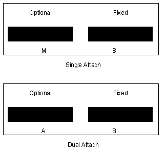
Configuring an FDDI port
The FDDI ports should only be configured as Dual Attach when the LS1200 is connected into a Dual Attach ring, refer to Figure 6. Connecting to FDDI.
To change the LS1200 configuration from Single Attach to Dual Attach follow these steps:
The following diagrams illustrate the different configurations using the LS1200.
Connecting an LS1200 to a Whisper on a FDDI Network
To connect a system of Whisper stations on an FDDI Dual Attach Ring to a LS1200, refer to part 1 of the following figure. In this figure the Whispers are connected into the FDDI dual ring configuration through ByPasses. The ByPass is responsible for connecting and disconnecting the station from the ring, and for closing the ring when the station is not active. When a station is inactive it is disconnected from the ring and only the active stations are connected together and thus leaving the ring intact.
In a Star configuration (part 2 of the following figure) the Whisper stations are connected to the FDDI ring through a concentrator, which electronically connects and disconnects the inactive station(s) from the FDDI ring and this improves ring reliability.
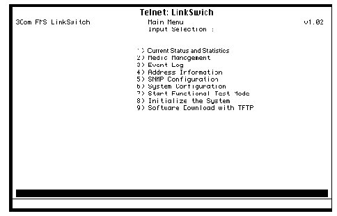
You can communicate with the LS1200 over the network using any Telnet facility that emulates a VT100 terminal (you can use any Mac on the network supporting this mode or any UNIX station).
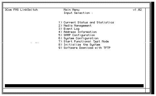
Note: If the LS1200 does not have an IP address, see the SNMP configuration procedure to set an address.
Ageing Timer
The ageing timer implements a timeout filter mechanism which results in the removal of the stations MAC address (physical Ethernet address).from the address table if there has not been a packet transmission from that station within the timeout interval.
When there are SciNet stations
connected to the Ethernet ports of the LS1200, you should
disable the ageing timer mechanism by changing the timer
value to 0. This prevents the MAC address table in the
Switching Hub from being automatically refreshed. It is
however recommended to refresh these tables on a regular
basis every few months, depending on the number of
stations in your network.
To refresh this table, change the timer from 0 to 1, wait
five seconds and then change it back to 0. The LS1200
tables can contain upto 1000 MAC addresses.
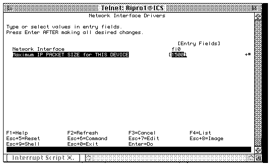
To enable NFS connectivity between FDDI and Ethernet via the LS1200, you need to change the FDDI packet size on the Ripro.
To change the size of the packets transferred, proceed as follows:
The Redundant Power System (RPS) supplies a DC power source providing redundant power to create a fault-tolerant environment.
The RPS contains two bulk power supplies, each of which is capable of powering all the attached components in the event of a failure of the other supply.
The RPS has two cooling fans for heat generated during operation. If the internal temperature of the RPS rises to an unsafe level a fault signal is sent to the LS1200 and the yellow OVERTEMP LED on the front panel illuminates.
Up to four LS1200 can be connected to a single RPS unit which can be mounted in a standard 19-inch rack.
The LS1200 attachs to one of the four DC connectors on the back panel, and the two AC input connectors supply power to the unit allowing for two separate AC power sources.
Installation
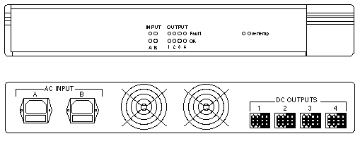
Front Panel LEDS
Input LEDs
Indicate the status of the corresponding AC input power
ports on the back panel (A, B).
| LED color | Indicates... |
| Off | No AC power at the port |
| Green | AC power at the port. |
| Yellow | AC power at the port; a fault is present |
Output LEDs
Indicate the status of corresponding DC ports (1-4) on
the back panel.
| LED color | Indicates... |
| Off | No DC power at the port |
| Green | Unit connected at the port. No DC output faults. |
| Yellow | Unit connected at the port. DC output fault. |
Overtemp LED
This yellow LED indicates when the internal operating
temperature of the RPS rises above a safe level or when a
fan failure occurs.
BackPanel
AC Power Inputs
Two standard connectors for AC power (A, B). Should be
connected to separate mains cicrcuits.
DC Power Outputs
Four standard DC output connectors, one for each unit
powered by the RPS.