Home | Contact Us | Submit Troubleshooting Info | Search | Help
Output | Software Solutions | Proofing | Color, Screening and Calibration | Scanning | Digital Photography | Consumables | POS
Home | Contact Us | Submit Troubleshooting Info | Search | Help
Output | Software Solutions | Proofing | Color, Screening and Calibration | Scanning | Digital Photography | Consumables | POS
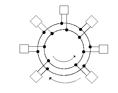
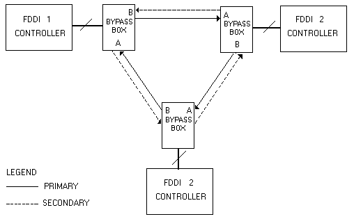
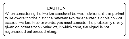
Protocol InformationFDDIWhat is SciNet/FDDI?SciNet/Fiber allows Scitex systems to communicate over a fiber optic network at the rate of 100 Mbits/sec. Up to 500 stations may be connected to the network. The maximum length between operational stations is 2 km with an overall maximum distance of up to 100 Km (60 miles). FDDI (Fiber Distributed Data Interface) is the standard protocol used for SciNet/Fiber networks. FDDI uses dual, counter-rotating rings to obtain enhanced reliability. All Scitex systems on the fiber optic network are connected to two parallel fiber rings via a special cable. Either of these rings acts as a backup if the other ring breaks at any point. FDDI Topology: FDDI Basics and TerminologyFDDI is a synchronous, token-passing type network and employs a fiber optic dual-ring topology. By virtue of FDDI's design, a network malfunction on one or more stations will not disable the network. The system will compensate for the problem and the effective data transfer rate will be unaltered. Each station has an "A" and "B" link in the network. Each of these links always has a Primary and Secondary fiber. The Primary fibers are used during normal transmissions. Normal transmission on FDDI is referred to as THRU. During THRU, the "B" link's primary fiber is for Transmitting while the Secondary fiber is for receiving. For the "A" link, the Primary fiber is for Receiving and the Secondary fiber is for Transmitting. FDDI Thru Connection: A station's FDDI controller normally receives the signal on the incoming cable and regenerates it for transmission on the outgoing cable. Regenerated signals may be reliably transmitted over a maximum distance of 2 km. The Bypass Box is responsible for maintaining network integrity, even if one of the stations on the network is disconnected. All connections to each FDDI station are made through the Bypass Box where there are 2 fiber optic cables and one control cable. The function of the control cable is to enable or disable a station's connection to the network. For example, when there is no power to the station, it will not be connected to the network and the Bypass will pass (not regenerate) the signals from the incoming cable directly to the outgoing cable.
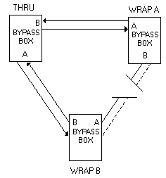
Normal tranmission on FDDI is referred to as THRU. If the "A" connection on a particular station should be disabled for any reason, then the "B" connection for that station takes over the task of both primary transmitter and primary receiver. This abnormal condition is referred to as WRAP B and signifies that a problem is present. The network, however, is fully functional with no degradation of throughput. Likewise, if the "B" connection should be disabled, then "A" performs the task of both primary transmitter and primary receiver. This condition is referred to as WRAP A and, again, signifies a problem. A Broken Cable on FDDI: SciNet / Fiber SpecificationsMaximum Distances Between Furthest Network Points: 100 km (60 miles) Between Adjacent Stations: 2 km maximum length Maximum Distances vs Station No. Maximum ring latancy = Dmax
NOTE:
Protocols
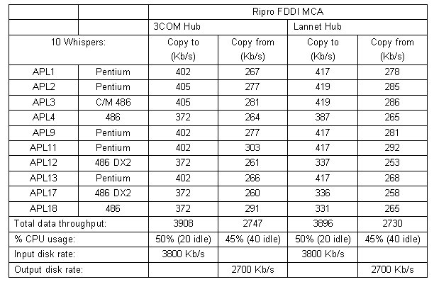
Performance The table below shows the test results of the system's performance when it is equipped with the SciNet FDDI board. Similiar results were achieved using the 3COM switching hub or the Lannet switching hub (currently under evaluation). The performance tests were
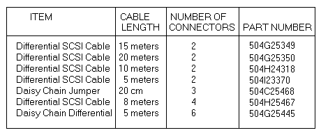
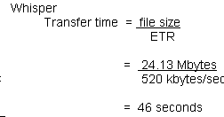
performed on Ripro Serve 41T connected to Megadrive RAID. SCSISCSI Networking - General DescriptionSciNet/Cluster uses SCSI (Small Computer System Interface) for networking Response systems in close proximity. A cluster is a group of Response systems or devices on a single SCSI bus. In keeping with the SCSI limitations, a cluster cannot contain more than 8 systems or devices and stations must be situated in a confined area enabling the cable length to remain within 25 meters. SCSI has a 1.5 Mbytes/second bandwidth. The Scitex implementation provides an approximate 520 Kbytes/second effective disc to disc file transfer rate. When networking systems with SCSI, a differential SCSI cable connects the systems. In Whisper systems the SCSI bus is connected to the Whisper MDC board through the system SSA board, which converts the differential SCSI to single-ended SCSI and the reverse. Response systems of the same type or systems in a mixed environment can communicate via SCSI. SCSI Networking Specifications
Example of Performance Calculation This example illustrates file transfer of an 8.5" x 11" CT file with resolution of 10/mm. File size = height x resolution x width x resolution x 4 bytes/pixel
Effective transfer rate = 520 kbytes/second
SCSI Networking Cable Requirements & LimitationsThe following are the requirements for differential SCSI cabling:
EthernetEthernet - IntroductionEthernet Capabilities & Specifications SciNet/LAN allows Scitex systems to communicate over a local area network at distances up to 2.5 kilometers. The protocol for local area networking is Ethernet or Thin Ethernet (IEEE 802.3 10BASE5 and 10BASE2). The LAN Controller installed in the Response-300 manages local area networking of Scitex systems over both Ethernet and Thin Ethernet. The LAN has a 10 Mbit/sec (1.25 Mbyte/sec) bandwidth. The Scitex implementation provides an approximately 420 kbytes/sec file transfer rate between Fyrox systems, and up to 800 between Whisper systems. Description of Process Ethernet is based on the IEEE 802.3 standard. It is a networking methodology based on the Carrier Sense Multiple Access/Collision Detect (CSMA/CD) model. The protocol is implemented by having each station on the network monitor the cable (ether) for other stations' transmission and then refrain from sending its own transmission until it hears no other station. There is a small probabliity that two stations might decide to transmit simultaneously and, as a result, there will be a collision. Each station will detect the collision, abort its transmission, wait a random period of time and then try again, assuming that no other station has started transmitting in the meantime. The Ethernet model, therefore, consists of alternating contention and transmission periods, with idle periods occurring when all stations are quiet. Ethernet Options Two Ethernet standards are supported directly by SciNet/LAN: Ethernet and Thin Ethernet. Although SciNet/LAN directly supports 10BASE5 and 10BASE2, other Ethernet options are supported with the required adapters. Ethernet, Thin Ethernet, Twisted Pair (10BASE-T) and other types of Ethernet media may be mixed on a network path by using appropriate repeaters and transceivers. Ethernet (10Base5) 10Base5
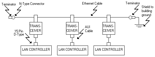
Ethernet: On Ethernet, systems can communicate over a distance of up to 2.5 kilometers. All systems on the Ethernet are connected to the Ethernet cable, which has a maximum length of 500 meters. Repeaters are used for longer distances. In a sample mixed environment of three Scitex systems on the Ethernet, each system is configured with the appropriate LAN Controller. The controller communications panel of the station is connected to the Ethernet coaxial cable through a transceiver. A terminator is attached at each end of the chain, one of which is grounded. The Ethernet cable is a single unbroken cable running externally for the length of all the systems. The cable is manufactured with marks at specified intervals, for transceiver connections. A terminator is attached at each end of the Ethernet cable, and one end is grounded. NOTE: The Ethernet cable can also be made up of shorter cables of certain lengths connected to each other by "barrel" connectors. The Ethernet option is used for greater segment length as well as the ability to support more nodes per segment. In addition, when comparing to "Cheapernet", Ethernet is more efficient in noisy areas such as newspaper environments. Cabling is more expensive since it requires the use of transceivers and special thick cables. New stations can be attached without disrputing the network. Thin Ethernet ("Cheapernet" - 10BASE2) 10
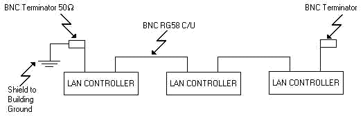
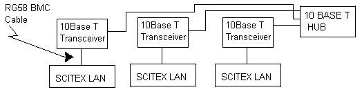
Base2 - Thin Ethernet ("Cheapernet"): Thin Ethernet ("Cheapernet") is a less expensive, functionally equivalent alternative to Ethernet, but is only effective for communication within a 925 meter range. The Thin Ethernet cable connects to the controller's communication panel BNC connectors, utilizing the controller's on-board transceivers. (Note: There are no transceivers to be installed as they are built-in on the board). The Thin Ethernet cable has a maximum length of 185 meters as opposed to 500 meters for 10BASE5. Repeaters may be used for longer distances. Adding new stations requires opening up the existing cable, at least briefly. The figure shows a mixed environment of Response systems on a Thin Ethernet subnetwork. Each system is configured with the appropriate LAN Controller, providing the connection from the system to the Thin Ethernet. The Thin Ethernet cable itself is attached to each controller panel or LANC Board. A terminator is attached at each end of the cable, and one end is grounded. Twisted Pair (10BASE-T) 10BaseT Twisted Pair: The Twisted Pair interface option requires that every station on the segment connect to a 10BASE-T Hub via the appropriate 10BASE-T Transceiver. Therefore, twisted pair employs a "star" topology as opposed to a single cable running across the length of all the systems. The transceiver-to-hub segment may be up to 100 meters. Depending on the type of transceiver used, Thin Ethernet or Ethernet interfaces may be mixed on the same segment. The greatest advantage to 10BASE-T is that it can use an existing telephone network. The twisted pair cables use RG45 type connectors. The disadvantage to using 10BASE-T is that it is significantly more prone to noise than 10BASE2 and 10BASE5, which can greatly reduce transfer rates. Devices for Linking Ethernet Segments in a Network There are various ways to link separate Ethernet segments in a network. They include Repeaters, Bridges and Routers. These are devices which are supplied and installed by outside vendors and must conform to IEEE 802.3 specification. Repeaters If an Ethernet segment has reached its maximum length, a repeater may be used when adding stations to the Ethernet LAN. A repeater is a device that receives a signal, amplifies it, retimes it, and then reconstructs the signal for retransmission. It can be used to interconnect different type segments of an Ethernet LAN (i.e.,10BASE5, 10BASE2, 10BASE-T, 10BASE-F, etc.). Bridges A bridge is a network device which is connected to two or more separate network media. For example, FDDI to LAN, one Ethernet LAN to another Ethernet LAN or distant LANs connected via telecommunications. Each media can have the full size allowed. The bridge receives all data packets transferred on all the media and checks destination addresses. Data packets intended for stations on one of the other media are automatically retransmitted on the correct medium. Bridges isolate traffic between the two interconnected network media. Only those data packets which are destined to the other network media are transmitted to the other media. For networks with high volume, this isolation is sometimes the reason a bridge is used instead of a repeater. In the SciNet environment, all media linked by bridges comprise a single subnet, since the work of the bridge is transparent to SciNet. When a bridge is used, the two portions must be configured with the same subnet name. There are two types of bridges which can connect Ethernet LANs and FDDI. An Encapsulation bridge transfers data from stations on one Ethernet LAN to stations on another Ethernet LAN through and FDDI backbone. A Translation bridge transfers data between stations on the Ethernet and stations on the FDDI by converting the data link protocols. The bridge is a device supplied by an outside vendor. Ethernet Specifications
Ethernet - Comparison Between Types of Physical Connection
**NOTE: 10BaseT is installed by customer (or by Scitex at user request). 10BaseT parts are supplied by customer. |