FDDI (IBM)
Fiber Single Ring
Adapter for the Scitex Ripro Server.
This document describes the
procedure for installation and configuration of the FDDI
(IBM)-Fiber Single Ring Adapter for the Scitex
Ripro Server.
Order of installation is as
follows:
- Install the upgrade kit.
- Perform configuration of
communication and networking.
FDDI Single Ring
Adapter
The FDDI Single Ring Adapter (Fiber
Distributed Data Interface) provides very high speed
local area networking over longer distances (up to 2km),
between stations with a single port handling of
bi-directional data handling. The Single Attach Stations
(SAS) are connected directly to the primary ring or via a
concentrator for communication between the workstations
and for communication with an FDDI dual ring. FDDI
cabling may be of three types: FDDI-Fiber, FDDI-Shielded
Twisted Pair (STP)or FDDI- Unshielded Twisted Pair (UTP).
On the Ripro Server, the only type Scitex supports is
FDDI-Fiber with a MIC connector.
The FDDI controller handles the
fiber optic communications, transmitting the data to and
from the host computer and remote systems.
In addition a Media Interface
Connector (MIC) is used to connect the cable to the
adapter.
The adapter is compatible with the
following protocol standards:
- ANSI X3.139 FDDI Token-Ring
Media Access Control (MAC).
- X3T9/84-48 FDDI Physical Layer
Medium Dependent (PMD)-for fiber interface.
- X3T9/83-15 FDDI Physical Layer
Protocol (PHY).
- X3T9.5/84-49 FDDI Station
Management (SMT).
- ANSI/IEE 802.2-1985 Local Area
Networks: Logical Link Control (in system
software).
Logistics
The following FDDI Single Ring
Controller Kit is used for the Ripro Server:

Installation of
FDDI Single Ring Adapter
The FDDI Single Ring Adapter Kit
consists of:
- FDDI-Fiber Single Ring Adapter
(Type 2-6).
- FDDI Cable
FDDI
Fiber Cable
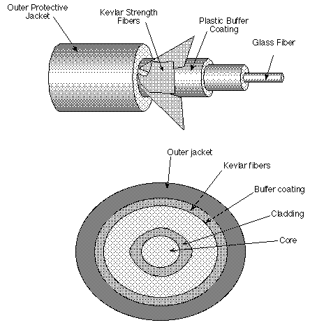
FDDI
Single Ring Adapter:
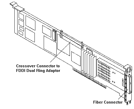
Shutting down the
system
Ver 1.1 Software
- Notify all system users that
the system will be shut down.
- At the UNIX prompt type logout
and press Enter.
- At the login prompt type in
shutdown, wait for the Halt is
completedconfirmation message at the end of this
shutdown process.
Ver 1.2 Software
- Logout from any CreoScitex applications that
may be running and verify that all other users have logged out and
that all Ripro volumes (on the Whisper or Mac) have been dismounted.
This process will take a few minutes.
- Type 3 Shutdown the System and
press Enter.
- If there are still dataVolumes
mounted, you will receive an appropriate message
and you will have to dismount these volumes.
- To perform a forced dismount,
type 2 SciSmit and press Enter.
- From the SciSmit main menu
select Communication and Servers and press
Enter.
- Select Ethershare and
press Enter.
- Select Stop EtherShare
Server and press Enter.
- Quit SciSmit and return to the
login menu.
- Type 3 Shutdown the System and
press Enter.
- Wait for the Halt is
completed... message before powering off the
server.
For models 55L, 570 and 58H
Set the power switches on the
attached devices to Off.
- Set the power switch on the
system unit to Off.
- Disconnect the system AC power
cable from the main power source.
- Use one of the two identical
keys to unlock the back cover.
- Unscrew the corkscrew shaped
lock shaft under the top cover next to the fan,
in order to release the front cover.
- Remove the back cover.
- Remove the front cover and
left side cover.
- At the back of the system unit
there are eight horizontal adapter slots; each
slot is covered with a bracket (for model 55L
there are only 4 adapter slots). Each
bracket is held in place by a black knurled knob.
- Select a vacant adapter slot,
unscrew the retaining black knurled knob and
remove the bracket.
- Insert the FDDI adapter.
- Connect the FDDI cable to the
FDDI adapter using the MIC (Media Interface
connector).
- Replace the back cover.
- Replace the front cover and
left side cover.
- Connect the AC power cable to
the main power source.
- Set the power switches on the
attached devices to On.
- Set the power switch on the
system unit to On.
- Continue to the configuration
procedure.
For model 34H
- Use the shutdown procedure as
described above.
- Set the power switches on the
attached devices to Off.
- Set the power switch on the
system unit to Off.
- Set the key mode switch to the
Service position to unlock the top cover.
- Disconnect the system AC power
cable from the main power source.
- Remove the rear cover.
- Loosen the three (3) top cover
screws at the rear of the top cover.
- Remove the top cover by
sliding it backwards.
- At the back of the system unit
there are 4 vertical adapter slots; each slot is
covered with a bracket. Each bracket is held in
place by a black knurled knob.
- Select a vacant adapter slot,
unscrew the retaining black knurled knob and
remove the bracket
- Insert the FDDI adapter.
- Connect the FDDI cable to the
FDDI adapter using the MIC (Media Interface
connector).
- Replace the top cover.
- Replace the back cover.
- Connect the AC power cable to
the main power source.
- Switch the key to the Normal
position.
- Set the power switches of the
attached devices to On.
- Set the power switches of the
system unit to On.
- Continue to the configuration
procedure.
For model 41T
- Use the shutdown procedure as
described above.
- Open the media door, rotating
the top of the door downward.
- Set the power switches on the
attached devices to Off.
- Set the power switch on the
system unit to Off.
- Set the key mode switch to the
Service position, remove the key from the
switch.
- Close the media door.
- Unplug the system unit power
cord, display power cord and attached device
power cords from power source.
- Remove the three cover screws
at the top of the panel at the rear of the system
unit.
- Gently remove the top cover as
described in the Installation and Service
Guide.
- At the back of the system unit
there are 4 horizontal adapter slots; each slot
is covered with a bracket. Each bracket is held
in place by a slotted thumbscrew.
- Select a vacant adapter slot,
unscrew the retaining slotted thumbscrew and
remove the bracket, sliding it to the side of the
system unit.
FDDI Adapter is full sized and can only fit in
the slot on the left side of the Mother Board.
- Insert the FDDI adapter.
- Connect the FDDI cable to the
FDDI adapter using the MIC (Media Interface
connector).
- Replace the cover, take care
not to damage any adapters that may stick out
slightly.
- Install the three cover
screws.
- Plug-in the system unit power
cord, display power cord and attached device
power cords to the power source.
- Insert the key and set the key
mode switch to the Normal position.
- Set the power switches on the
attached devices to On.
- Open the media door, rotating
the top of the door downward.
- Set the power switch on the
system unit to On.
- Close the media door.
Installing the
FDDI Driver
Ver 1.1
To install the FDDI driver you will need the CreoScitex
Distribution Media CD-ROM which consists of both CreoScitex and AIX
application software.
- Insert the CD-ROM into your
server.
- Login as root and press Enter.
- Type your password and press
Enter.
- At the command prompt type cd
/scitex/version/utils/admin and press Enter
- Type ./scitex_admin and press
Enter.
The Scitex Admin menu now appears.
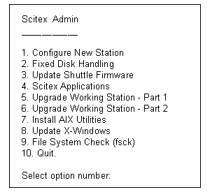
- Type 7 (Install AIX Utilities)
and press Enter.
The AIX Utilities menu appears.
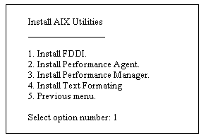
- Type 1 (Install FDDI) and
press Enter.
- Type y in answer to Do you
want to install...? and press Enter.
The FDDI driver is now installed.
- Type 5 (Previous menu) and
press Enter.
- At the Scitex Admin menu type
10 (quit) and press Enter to exit this menu and
return to the command prompt.
Ver 1.2
To install an FDDI driver.
- From the SciSmit main menu
select Communication and Servers and press
Enter
- Select FDDI and press
Enter
- Select Install FDDI and
press Enter.
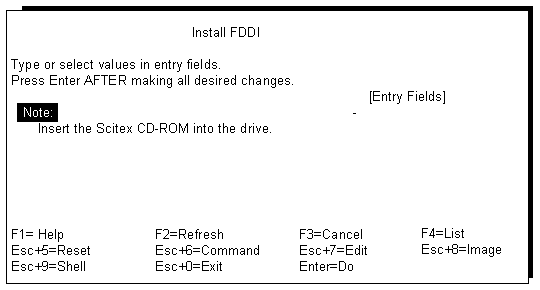
- Verify that the Scitex
Installation CD-ROM is ready and press Enter.
- Press Enter at the ... are you
sure? screen.
- The Command Status window will
display OK if the installation is successful,
press [F3] until you return to the SciSmit menu.
Networking
Overview
Scitex and foreign systems can
communicate over LAN with different types of cable. The
Ripro Server Communication is based on a LAN system and
is supported by NFS and TCP/IP suite of protocols which
has the following features.
- Network technology
independence- allowing TCP/IP to run on most
hardware.
- Universal interconnection- a
computer on one local network may communicate
with another either on the same network or on
another network as long as the local network is
appropriately configured.
- Application protocol
standards- Internet standards extend to a large
number of common applications, such as electronic
mail, file transfer and remote login.
The Ripro Server is also supported
by EtherTalk (an Apple networking system).
TCP/IP for the Ripro Server uses
the following adapter cards and connections:
- IEEE 802.3-Thin Ethernet.
- FDDI-(IBM) -Fiber, Single Ring
I/F
- 10BaseT
FDDI Topolgy
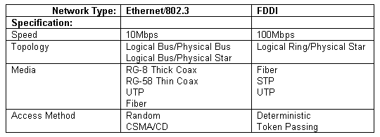
The FDDI network uses the fiber
optic cable as its transmission medium. Using this medium
it can achieve up to 100Mbps data rate, and can support
up to 500 stations using distributed clocking (time
sharing). A maximum length of 2km between stations and
over 20km between stations using single-mode fiber. Total
fiber length of up to 200km with a maximum of 500
stations.
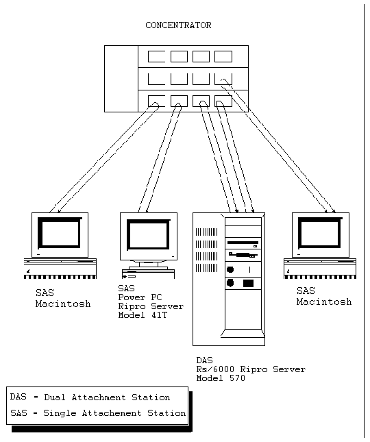
In a single ring network the Single Attachment Stations
have only a single port for handling of transmitting and
receiving.
FDDI-Fiber Single Ring Adapter
Provides communication link to the
concentrator, which links the workstations together to
form a ring. The concentrator has master ports to enable
attachment of other FDDI stations in a tree topology. The
number of workstations that can be attached to a single
concentrator is determined by the port capacity of the
concentrator. Each workstation can communicate directly
with any other workstation in the ring.
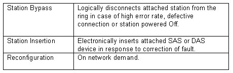
Connnection through an external
concentrator isolates the stations from the primary ring.
In the event of a workstation failure, or disconnect from
the concentrator, that workstation bypassed by the
concentrator and allows communications to continue.
The concentrator may have other
concentrators attached to it to increase the number of
stations in the ring.
FDDI
Single Ring Stand Alone Concentrator Topology:
FDDI
Concentrator Functions
LAN
Technology Basics-Summary
Typical
Network with FDDI and Switching Hub:
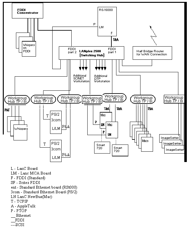
Network
Configuration
The following procedure describes
the configuration of communication and networking.
- Login as root, at the login
prompt type smit tcpip and press Enter.
- Press Enter to produce the
Available Network Interface list:
The following screen appears:
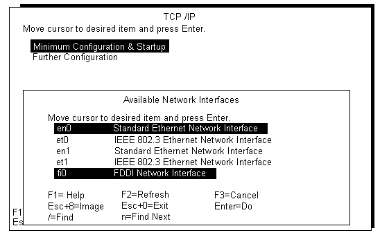
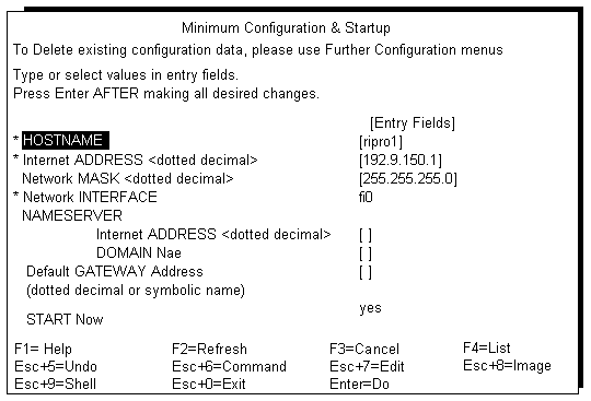
- Select the new network
interface to configure (fi0, FDDI Network
Interface) and use the following screen to enter
the configuration values.
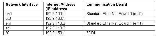
- Refer to Table 1 Network
Interfaces and IP Addresses for the list of
Network Interfaces and their corresponding IP
addresses.
Table
1: Network Interfaces and IP Addresses
NOTE:If there are other TCP/IP systems on-site,
the Network Administrator will issue you the appropriate
IP numbers.
Scitex IP Addresses
The following is the recommended
structure for Scitex IP Addresses:
| Station/Unit |
Recommended
Address |
First Ethernet Communication board
(ent0) on Ripro Server (Ripro1) |
192.9.100.X (X is 1-20) |
Second Ethernet Communication board
(ent1) on Ripro Server (Ripro1) |
192.9.110.X (X is 1-20) |
Third Ethernet Communication board
(ent2) on Ripro Server (Ripro1) |
192.9.120.X (X is 1-20) |
Fourth Ethernet Communication board
(ent3) on Ripro Server (Ripro1) |
192.9.130.X (X is 1-20) |
| FDDI Adapter (fi0) on Ripro Server |
192.9.150.X (X is 1-20) |
| Mac |
192.9.Y.[21-74] |
| PS/2 |
192.9.Y.[75-99] |
| Sun |
192.9.Y.[100-119] |
| Whisper |
192.9.Y.[120-149] |
Communication
units
(hubs, routers, switching hubs etc.) |
192.9.Y.[200-254] |
Examples
- Y-is determined by
the Network communication board on the particular
server. 192.9.110.25- is a Mac connected to the
Second Ethernet board on Ripro1.
- 192.9.150.125- is a
Whisper connected to FDDI through the Switching
Hub.
- The first Mac
connected to ent0 will have an address of
192.9.100.21.
- The first PS/2*
connected to the Ripro Server via the FDDI
adapter and Switching Hub will have an IP address
of 192.9.150.75.
- The first Whisper
connected to ent1 will have an address of
192.9.110.120
This section covers configuring the
AppleTalk network.
- Logout from the Scitex
application, at the login prompt login as root
and press Enter (Ver. 1.1).
- Logout from the Scitex login
menu (Ver. 1.2), login as root and press Enter.
- At the UNIX prompt, type: cd
/usr/local/es and press Enter.
- Type ./netconf and Enter (x2).
The following screen appears (this is an example
only):
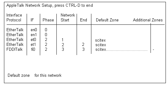
- For correct configuration at a
customer's site, the Network Start and End
numbers should be supplied by the Network
Administrator.
- After finishing the AppleTalk
configuration, press CTRL-D and then press Y to
write current network configuration.
- Press CTRL-D to exit netconfig.
- To activate the new segment on
the network, type at the prompt /stop-atalk
and press Enter.
This command announces to all network users that
there will be a system shut-down in 5 minutes.
For an immediate system shut-down type
./stop-atalk now.
- After AppleTalk is stopped,
and the shell prompt appears, type /start-atalk
and press Enter.
- The new network now appears on
the Macs Chooser.
NOTE:All Macs that have been moved from one
communication board to another must be restarted in order
for the new network to take effect.
Connectivity Test
This test is performed after the
FDDI adapter is installed in the server and the cable
connections executed:
- Server FDDI I/F to the LANplex
or LinkSwitch.
- LANplex or LinkSwitch to Macs.
Performing the Connectivity Test
over TCP/IP
- Ping from the server to each
PS/2* on the FDDI segment.
Performance Test
The test is performed over the
network at anyone time, and results of the test depend on
the amount of traffic over the network.
Ripro Server-
PS/2*
- Mount NFS between the PS/2*
and the Ripro Server.
- From each PS/2* (if any) on
the FDDI segment send a 20MB file to the Ripro
Server.
- Copy from the Ripro Server to
the PS/2* over TCP/IP and NFS
- Check how much time is taken
for the file transfer to complete and calculate
the Transfer Rate using the formula:
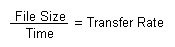
The Transfer Rate should be at least according to
following table:

Lantest
- On a Mac station that
communicates with the server through the
Switching Hub and the FDDI segment, open the
Chooser and select AppleShare, select the
zone and server.
- Enter your Username and
Password, select EtherShare Application.
- Open the EtherShare
Application on your desktop, open the Unsupported
folder and then select the Lantest file.
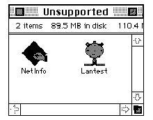
- Activate Lantest
utility, open the File menu in the menu
bar, Select Test Volume and select
the dataVolume for testing from the Ripro.
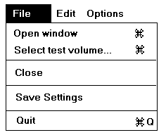
- Click Start to execute
the test.
Ripro Server- Mac
- 1. From each of the Macs on
the FDDI segment perform the Lantest.
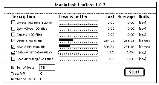
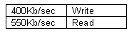
The Transfer Rate should be at least (for Quadra
or PowerPC Macs):
KIT,IBM FDDI FOR RIPRO
SCN:501R44011
| Scitex Part No. |
D e s c r i p t i o n |
| 138F00028 |
FDDI
CABLE ASSY L=15M DUALAN |
| 138F00029
|
FDDI
CABLE ASSY L=30M DUALAN |
| 510K41032 |
KIT,IBM
FDDI FOR RIPRO |
SCN:510K41032
| Scitex Part No. |
D e s c r i p t i o n |
| 399Z39900A |
FDDI
(IBM) Single Ring Adapter |
| |
Installation
Guide |
| 605A40095 |
FDDI-FIBER
SINGLE-RING ADAPTER |
| 630P10090 |
FDD S/W OTC |
|

