Installation
of SegWay Port Switch Hub
The SegWay Managed Port Switch is a
workgroup hub that allows per port switching of any of
its 24 fully compliant IEEE 802.3 10BASE-T ports to any
of eight independant Ethernet Channels (segments).
Each SegWay Port Switch hub unit
supports 24 10BASE-T ports which (each of the 24 ports )
may be independently switched onto 8 discrete Ethernet
segments.
All 8 SegWay Ethernet segments may
be connected, using eight 10BASE-T backbone ports via
10BASE-T cabling (up to 100m in length), to a Swiching
Hub (e.g. LANplex2500).
The SegWay Managed Port Switch
supports two types of Ethernet media:
- Unshielded Twisted Pair
(10BASE-T) cabling.
- Shielded Twisted Pair cabling.
The SegWay Managed Port Switch
provides full management using any SNMP based network
management platform.
It can also support a management
interface using an RS-232 console port connected to a
personal computer or workstation running VT-100
compatible terminal emulation software.
There is also the option of an
onboard LCD/Joystick combination for configuring,
monitoring and managing the Port Switch.
- The following two network
diagrams display the use of a Segway Port Switch
Hub in Scitex sites, in comparison to TP8/i
workgroup Hub connections.
Typical
Network Configuration with SegWay Workgroup Hub
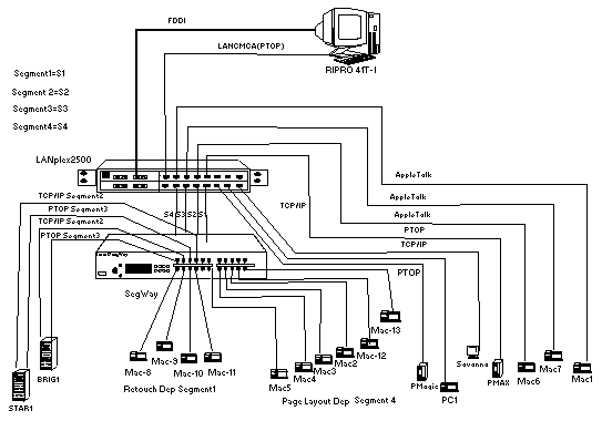
Network
Configuration with TP8/I Workgroup HubNetwork
Configuration with TP8/I Workgroup Hub
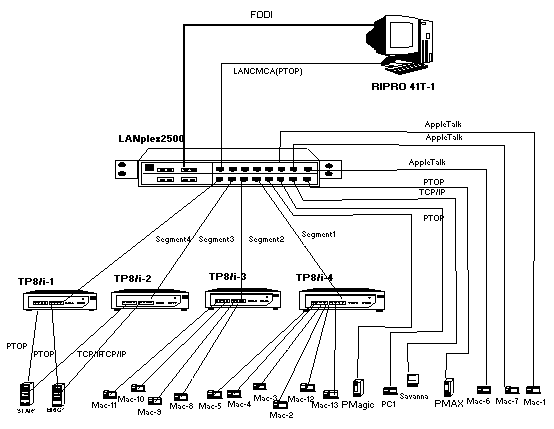
The SegWay Managed Port Switch is
usually installed in a communication rack.
- Attach rack mounting ears to
each side of Port Switch unit .
- Place rack mounting ears
against side of rack (using screws provided),
tighten the screws.
- Connect network devices.
- Connect the SegWay to an AC
power outlet 100/120V or 200/240V.
SegWay
Base Front Panel

SegWay
Base Back Panel

To access the Terminal Manager,
connect the RS-232 console port to a personal computer or
workstation running VT-100 compatible terminal emulation
software (use the 9-pin male "D" connector).
Entering
Commands
- Type in the first two letters
of the command and then press the Spacebar
to complete the command.
- Each command must be followed
by a [Return/Enter].
- To list possible completions
for different sets of commands, press ?
- Type login at the
LANart prompt and press Enter.
LANart> login
Password:********
- Type in nopasswd and
press Enter
The following message appears:
Administrator
logged in.
LANart>?
Possible completions:
help
auto-config
disable
enable
load
login
logout
ping
reset
rz
set
show
store
Enable Communications
LANart> enable
port all
LANart> enable snmp
LANart> enable telnet
Set IP Address
LANart> set
IP-address
Possible completions:
<decimal number between 0 and 255 followed by a
dot>
LANart> set IP-address 192.9.150.210
LANart> set subnet-mask 255.255.255.0
- To verify the configured IP
address use the following commands:
LANart> show
IP-addresses
SegWay IP Address: 192.9.150.210
Subnet Mask: 255.255.255.0
Default Router IP Address: 192.9.100.1
Trap Server 1 IP Address: 0.0.0.0
Trap Server 2 IP Address: 0.0.0.0
Assigning a port or group of
ports to a channel
The syntax for this command is:
set <group
#>.<port #>through<group>.<port #>
<channel #>
where:
| Group # |
Workgroup hub # (LANart Port
Switch#) |
| Port #
|
Number of first port in group/single
port to be assigned to channel #
Number of last port in group/single port to be
assigned to channel # |
| Channel #
|
Channel (1-8) to which ports
assigned |
NOTE:
For Scitex configurations the Group # is always 1.
Example:
LANart> set 1.1 through 1.6 channel 1
LANart> set 1.7 through 1.12 channel 2
LANart> set 1.13 through 1.18 channel 3
LANart> set 1.19 through 1.24 channel 4
In the above example:
1 is the workgroup hub #, 1.1 through 1.6 are
the port numbers and 1 is the number of the
channel to which they are to be assigned.
1 is the workgroup hub #, 1.7 through 1.12 are
the port numbers and 2 is the number of the
channel to which they are to be assigned and so on.
Storing the configuration
- When the configuration is
complete it should be stored in the user-config
configuration set.
- Each configuration can be
stored in one of four port configuration sets (preset
- 1 to 4). These sets do not store the entire
configuration
- A complete configuration is
defined as user-config, in which case when
the SegWay is loaded after booting(power
up) this is the default configuration. This is
particularly important in the event of a power
failure for example, since the current setup
stored in here is stored to a non-volatile
memory.
LANart> store
Possible completions:
preset-1
preset-2
preset-3
preset-4
user-config
LANart> store preset-1
Preset #1 stored.
LCD Console
Operation
The LCD Console consists of
a joystick, two buttons, an LCD display and an eight
channel activity LED board.
- Use the joystick to
navigate through the menus.
- To return back to the menu
from a specific command press the Home
button.
- To enter the value of a
parameter in the display press the Enter button.
To display Segment
Status follow these steps:
- Press the Home button a
few times until the LCD console displays the Configure
menu.
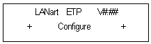
- Move the joystick right step
by step until the console displays the Statistics
menu.
- Continue moving the joystick
right step by step through the Ping menu
until the Display menu appears.

- Move the joystick down
until the Segment Status appears in the LED
display.

- Move the joystick down again
to display the ports linked to the channels (as
in the example from the previous page).

The following symbols can also
appear for Port Status:
| . |
Port OK |
| A |
No Activity |
| C
|
Corrected
Polarity |
| D
|
Disabled |
| J |
Jabbering |
| L
|
Link Down |
| P
|
Partitioned |
| S
|
Security
Violation |
|

