Site Planning
Workflow
Network
Infastructure - 10Base-T
The IEEE 802.3 10Base-T standard
network provides 10 Mbit /sec Ethernet networks using
twisted-pair cables. The advantages of twisted pair
wiring over other types of media are
- low cost
- simplicity in configuring the
network
- ease of locating problems in
the network.
All cabling infrastructure should
be prepared to support future 100 mbit/sec
connectivity(ATM, etc).
The ANSI EIA/TIA-568 document sets
out the standards of infrastructure installation
- The maximum horizontal
distance shall be 90 meters (295 ft) independent
of media type.
- The maximum horizontal cable
length has been specified with the assumption
that a maximum length of 3 meters (9.8 ft) of
cable with the same characteristics as that of
the horizontal cable, has been used in the work
area.
- A minimum of two
telecommunications outlets shall be provided for
each individual work area (it is not necessary
that they be on separate face plates).
- It is desirable that hardware
used to terminate UTP cables be of the insulation
displacement contact (IDC) type.The
infrastructure cables should not be connected to
wall sockets or to patch panels (locating in the
communication rack).
- When adaptations are needed in
the work area, they shall be external to the
telecommunications outlet.
- Some telecommunication
equipment (e.g., ISDN terminals) require
termination resistors in the work area. This
shall be accomplished by placing the termination
resistor external to (not integrated into) the
telecommunications outlet.
- Passive adapters may be needed
when the cable type (media) required by the
equipment in the horizontal wiring is different
from the cable type (media).
- This requirement specifically
prohibits the use of flat, non-twisted cords in
the 100-OHM UTP wiring system.
- Between any two devices on the
network ,there may be:
- Up to 5 link segments.
- Up to 4 repeaters or
concentrators.
The EIA/TIA-568 standard also deals
with media specifications.
There are 4 types of media
specified by the standard.
- 150ohm STP cable.(TYPE1)
- 100ohm UTP cable.(PDS)
- 50ohm Coaxial Cable
- 62.5/125Micron Multimode
Fiber.
The EIA/TIA-568 standard appendix
lists several other wire types:
- 100ohm STP (S-UTP)
- Other Multimode Fibers Optic.
- Singlemode Fiber Optic Cable.
- 75ohm Coaxial Cable
- Undercarpet Cables.
Scitex supports the following
infrastructure cables:
- The infrastructure cable (the
cable running from the communication rack to the
work stations) must be comply with category 5 UTP
(unshielded twisted pair) 100ohm standard.
- This cable must have the
capacity to transfer data upto 100 Mbit/sec
band-width.
- All 10Base-T network
components should comply with category 5, UTP
(unshielded twisted pair) or S-UTP cable type
standards.
- In the case where there is a
country or customer that requires shielded
infrastructure standard cable, the type of
infrastructure cable should be standard 10Base-T
STP 100ohm cable or Type 1 (IBM) cable type
150ohm STP (shielded twisted pair ) cable. In
this case all 10Base-T network components must be
of the shielded kind complying with category 5
standards.
There are two possible 10Base-T
physical connections:
- Connect 4 wires from 2*4 (8
wires) to the communication sockets and to the
patch panel. This option enables connecting 2
different workstations on the same infrastructure
cable.
- Full connection complying with
category 5 standard.
4 twisted pair cables fully connected on both
sides of the category 5 infrastructure cable
(communication sockets and patch panel)as
follows:
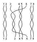
The patch cable should also be full category 5
standard connection.
Scitex requires installing the network
infrastructure to meet the full category 5
standard.
The 10Base-T network components
should be as follows:
- A 19" communication rack
(20U or 44U) equipped with an exhaust fan unit on
the top of the rack, one group of 8 electricity
sockets and a front door with a lock.
- All active and passive
communication devices (switching hubs, workgroup
hubs, 10Base-T patch panels and/or fiber optic
patch panels) are placed inside the communication
rack.
- Communication 10Base-T patch
panel containing 16 RJ45 female connectors
complying with the category 5 standard.
- Patch cable 4*2*26# ftp (flex
twisted pair) category 5 ISO/IEC with RJ45 male
connectors on both ends of the cable, complying
with the category 5 standard.
Cable lengths:
| 5 meter cable |
Wall cable - for
connecting work stations to the network. Connect
one end of the cable to the communication socket
placed on the wall and the other end of the cable
to the proper 10Base-T transceiver which is
plugged-in to the work station, or directly to
the workstation. |
| 1.5 meter cable |
Patch cable - for
patching from each RJ45 female connector type to
ports of the communication devices, (switching
hub, workgroup hub etc) and to the proper RJ45
female connector on the patch panel. |
- Infrastructure cable 4 twisted
pair 24 awg ( twisted number for 1 meter)
equivalent to category 5, 100ohm standard.
There are some category 5 standards which have
equivalent substitutes from different working
group:
- E IA/TIA category 5
- UL level 5
- NEMA, a low-loss extended
frequency premises telecommunication cable.
- 10Base-T communication sockets
equipped with single or double RJ45 female
connectors complying with the category 5
standard.
- 10Base-T transceivers connect
to all Ethernet workstations.
There are 3 kinds of 10Base -T trancievers:
- AUI to RJ45 type, used for
connecting all Scitex workstations, Ripro
Server LANC MCA boards,all Scitex Sun
platform type, Mac connecting with LANC NuBus
LANC board. There are some "old"
Macs (2ci,fx,2fx,lc) which have a standard
Ethernet board connecting to the multibus, in
this case also use the AUI to RJ45 type of
10Base-T transceiver.
- AUI to BNC type for
connecting all Scitex workstations to a
10Base-2 (chipernet) network.
- AAUI to RJ45 type for
connecting Macs equipped with built-in AAUI
connectors.
- Marking:
The communication rack should be marked as
follows.
Communication
Rack 1 etc... (in case there are more than
one communication racks).
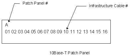
The first 10Base-T
patch panel should be marked A, with all the RJ45
female connectors marked systematically from 1 to 16,
the next panel should be marked B with all the RJ45
female connectors marked systematically from 1 to 16
and so on.

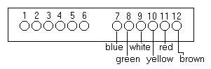
- The fiber optic patch panel
should be marked from 1-12. Adjacent to each
number the color of the fiber must also be
listed.
A
Fiber Optic Patch Panel
- The 10Base-T sockets should be
marked as in the following example:
- It is recommended to mark the
cable located in the communication rack running
from the switching hub to the patch panel«.
|

