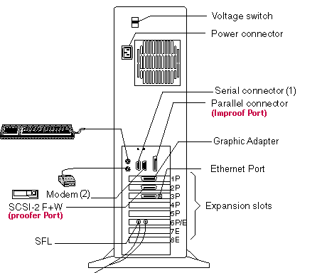
Make sure that the power supply voltage switch on the E 30
PowerPC is set to the appropriate voltage (115V or 230V).
Connect keyboard cable to KB (6-pin miniature DIN)
connector.
Connect mouse to Mouse (6-pin miniature DIN)
connector.
Connect the monitor cable to the PowerPC`s S15 (15-pin)
connector.
Connect the modem cable to the modem and to the PowerPC`s COM 2 (DB-9) connector
(a telephone line should be connected to the modem's RJ-11 LINE connector).
Refer to section Remote Support and Control
via Modem.
Connect the Ethernet network cable to the network and to IBM
Standard Ethernet or Fast Ethernet adapter.
Figure 1-5. Back View connections
Connect optional devices to appropriate connectors (i.e.
connect optical drive or DAT to 50-pin SCSI II connector, or parallel printer to Parallel
connector).
After connecting all interface cables, connect power cables
to devices' power connectors and to electrical outlets (the Brisque, monitor,and modem
each have separate power supplies).