

Home | Contact Us | Submit Troubleshooting Info | Search | Help
Output | Software Solutions | Proofing | Color, Screening and Calibration | Scanning | Digital Photography | Consumables | POS
Home | Contact Us | Submit Troubleshooting Info | Search | Help
Output | Software Solutions | Proofing | Color, Screening and Calibration | Scanning | Digital Photography | Consumables | POS
Installation (F50)
Hardware Installation
Hardware Installation
Assembly of Components
To assemble the components of your Brisque refer to the following publications which are supplied with your unit:
Model RS/6000 7025 F Series
Refer to the following diagram for the location of the Brisque rear components.
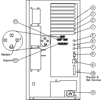
Figure 1-5. F-50 Rear view
| # | Component | Description |
| 1 | Ultra SCSI (slot 1) | For internal disks only |
| 2 | Fast Ethernet (Slot 2) | For Ethernet communication |
| 3 | Graphics (Slot 3) | Graphics adapter |
| 4 | SFL-TSP (Slot 5) | For fiber communications. |
| 5 | Mouse Connector | For mouse connection |
| 6 | Keyboard Connector | For keyboard connection. |
| 8 | Ethernet - AUI | 10BaseT - not in use |
| 9 | Ethernet - Twisted Pair | 10BaseT - can be used for Lotem connectivity only |
| 10 | On board SCSI | External connector for devices,Iris, opticals etc |
| 11 | Power connector | For connecting power cable |
| 12 | Parallel connector | For connecting an Improof. |
| 13 | Serial (Com1-3) | For connecting a Modem (Com 2) or other serial devices |
Refer to the following diagram for the location of the Brisque front components.
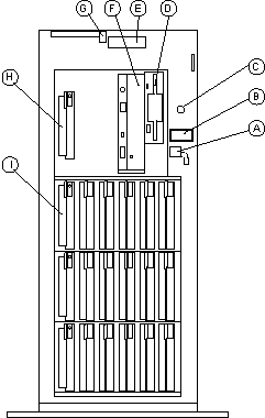
Figure 1-6. Brisque Front View
| # | Component | Description |
| A. | Keylock | For locking/unlocking front cover |
| B. | Power On/Off | Turns the computer power on and off. |
| C. | Reset button | Resets computer |
| D. | 3.5" floppy disk drive | Floppy disk drive |
| E. | Operator display Panel | LCD panel, displays system configuration information |
| F. | CD-ROM drive | CD-ROM drive |
| G. | Power On Led | Glows when the computer is on. |
| H. | Upper Hard Disk Bays | Bays for system disks |
| I. | Hard Disk Bays | Bays for Data Disks |
Installation Procedures
During installation, refer to Component Diagrams, for information on the location of Brisque components.
 |
Do not connect any power cords before all components have been connected to the Brisque. |
Refer to Figure 1-5. F-50 Rear view for position of slots.