Procedure |
|
Note: This procedure takes 3 days to implement.
- Replace the Dynamic optics
assembly.
- Replace the Static optics assembly according to the procedure
in FCO 21662.
- Replace the old Standard controller with the new one
supplied.
- Route the new spinner cable from the Standard controller to the left side
of the Dolev. The cable routing is similar to LDR cable for the new Static
optics assembly. Route both cables, if you are replacing an old Static optics
assembly. (Refer to the section Replacing
the Static Optics Assembly for more details).
- Attach the noise absorbers to the mainframe.
- Perform the Dolev 800V Diagnostics.
- Check and adjust the focus, the Bow, and the
registration.
Important: Do not use the existing spinner alignment and bow jigs.
Use only the modified jigs.
- Calibrate the machine offsets, Resolution/Intensity table and
perform ATP for customer approval.
Removing the Dynamic optics assembly
- Move the roller (spreader) to End Position. This is important
to allow free passage of the carriage along the Lead screw.
- Move the carriage to Position 400.
- Power off the imagesetter using the control panel ON/OFF
switch.
- Open the left and right service doors.
- Remove the light-proof cover from both sides of the Dolev 800.
- Dismantle the fiber optics connector as follows:
- Place an optics cover over the tip of the cable.
- Secure the cable in a safe place where it will not be damaged.
- Disconnect the fiber optics cable harness from the mainframe .
- Disconnect the ground cable.
- Dismantle the stepper motor. Make sure you pull out the cross
adapter, or the rubber adapter which connects the stepper motor to the Lead screw.
- Loosen the screws that hold the left side bearing housing.
- Gently pull the Lead screw out, with the optics carriage
attached, until the bearing is out of the right side bearing housing.
- Pull the Dynamic optics assembly out by grasping the optics
carriage. Do not grasp the Lead screw!
- Pull the Dynamic optics assembly until the carriage is out of
the drum but still resting on the guide beam.
- Connect the Lead screw holder (280B34179) to the Dynamic
optics coupling. Tighten it well. This jig holds the Lead screw to the carriage after
removing the fork.
- Pull out the Lead screw with the carriage, and place it on a
lint-free cloth.
- Disconnect the Lead screw holder from the carriage. Separate
the carriage from the Lead screw.
Important: Do not let any oil to come into contact with the Lead
screw or the guide beam.
Assembling the new Dynamic optics
assembly
- Important: If FCO 20674 was not implemented, do the
following:
- Install the Vertical Bar and the Beam Adapter to the left
support beam of the optomechanics.
- Lock it 2 mm from the chassis wall.
- Connect the Lead screw to the new Dynamic optics assembly, as
follows:
- Fasten the Lead screw holder to the carriage.
- Tighten the cup securely, to make sure that the Lead screw does not fall from the
carriage and get damaged during assembly.
- Put the Dynamic optics assembly in place on the guide beam.
When pushing the Lead screw into its final position, make sure the bearing fits the
housing. Enter the right bearing into the housing from the right side of the machine.
- Assemble the left side housing. Do not tighten the screws.
- Push the adjustment pins into their holes in the bracket. Use
the adjustment plate to fit the bracket in its correct place and tighten the screws.
- Assemble the stepper motor in place together with the Lead
screw coupling.
- Reconnect the fiber optics cable, as follows:
- Reconnect the ground and the cable holders.
- Connect the LD adapter cable (504L1L043 ) to the single cable
from the Dynamic optics assembly.
- Reconnect the cable harness from the Dynamic optics assembly
to its original position on the mainframe.
- Use the Lead screw handle to move the carriage to the home
position. Make sure that the "flag" enters into the center of the slotted HP
detector. If not, adjust the location of the optical switch.
- Repeat Step 7 with the end position detector.
Replacing the Static Optics Assembly
If an old Static optics assembly is
installed, replace it using the following FCO 21662 procedure:
- Power off the imagesetter.
- Dismantle the Static optics assembly and the
RF driver.
- Install the supplied Static optics assembly in
the position in which the dismantled Static optics assembly was previously located. Use
the left and the center screws which held the old Static optics assembly in place.
- Connect the fiber cable to the fiber
connector.
If a new Static optics assembly is installed,
replace it using the following procedure:
- Turn the imagesetter off.
- Replace the Static optics assembly with the
new Static optics assembly supplied.
- Remove the Standard controller.
To replace the Standard controller:
- Remove the Standard controller.
- Route the new spinner cable from the Standard controller to the left
side of the Dolev. The cable should enter the dark area through the
hole that is covered with the plastic cap on the left side. Insert the
cable from the inner part of the dark area and then route it to the
Standard controller. Make sure that no light penetrates the dark area.
- Route the LDR cable from the Standard controller to the Static optics
assembly.
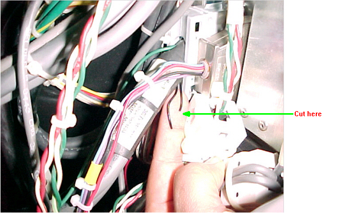
- Cut the black loop near the harness as shown in fig_1,
this will indentify the dolev as dolev 800V.
- Install the two Relay driver boards, CPU board, fast stepper driver
& CRI boards from the old Standard controller on the supplied new
Standard controller as follows:
- Remove the two Relay driver boards, CPU board, fast stepper driver
& CRI boards from the old Standard controller.
- Install the two Relay driver boards, CPU board, fast stepper
driver and the CRI boards in the new Standard controller.
The noise absorbers should be attached to the side covers,
rear cover and to the film loading doors of the mainframe.
- Attach the noise absorbers according to the illustrations
supplied.
- Make sure that the noise absorbers do not cover any ground
connection.
Before you run the diagnostic test do the following:
- Make sure that all the cables are connected properly.
- Insert the diagnostics diskette in the diskette drive.
- Turn on the imagesetter.
Perform the Dolev 800 diagnostics (Ver 1.04A), making sure you check
the new boards and do the following:
- Run CRI / NVM / DESTRUCTIVE to clear all the tables. You must
clear all tables.
- Check and adjust the Home Position detector.
- Run DIAG / UTIL / MECHANICS / CARRIAGE to move the carriage
from side to side. Make sure that the movement is smooth and that the harness and the
chain do not get caught in the spreader.
- Run DIAG / MOTOR / CARRIAGE / Feed Position to adjust the Home
Position detector.
- Check the light calibration in the Util mode.
- Check the new spinner.
|