Home | Contact Us | Submit Troubleshooting Info | Search | Help
Output | Software Solutions | Proofing | Color, Screening and Calibration | Scanning | Digital Photography | Consumables | POS
Home | Contact Us | Submit Troubleshooting Info | Search | Help
Output | Software Solutions | Proofing | Color, Screening and Calibration | Scanning | Digital Photography | Consumables | POS
Dolev 800 - Loading/Unloading System -
Feeder Motor
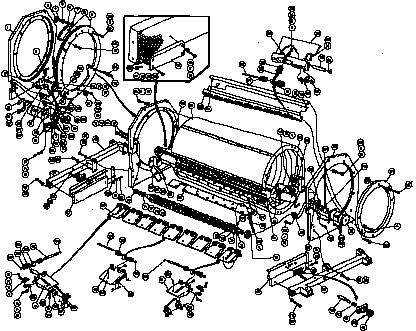
Optomech 800P (click to see image)
Description
Replacement
Check
Feeder Shaft
Adjustment Procedure
Dolev 800
Width Offsets Adjustment
The Feeder Motor (#110) is located on the optomechanical assembly. It is a
bidirectional motor responsible for turning the Feeder Shaft. The feeder shaft
supplies the film to the drum. The motor is located on the right side of the
machine.
Tools
and Accessories
Disassembling the
Feeder Motor
Assembling the Feeder
Motor
Flat screwdriver
Set of Allen keys
Melicot Grease
Marking pen
Masking tape
Enter the diagnostics program. Select UTILITIES, MECHANICS. Select 5. Feeder from the Mechanics Menu.
Mechanics Menu
| 1. Carriage | 2. Roller | 3. Spinner |
| 4. Cassette | 5. Feeder | 6. Cutter |
| 7. Vacuum/Valve | 8. Others | 9. Detectors |
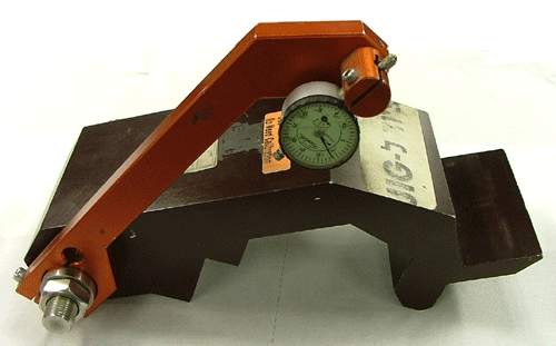
Adjusting
the Feeder Wheels Offset
Adjusting the Spreader
Offset
(Width Offset in the Plotter Description Table)
The Width Offset parameter refers to the relevant offset from the index pulse.
From this position the plotter will start positioning the Exposure data. The
offset bypasses the area where the laser beam hits the pressure rollers and
the mechanical elements. This parameter is measured in millimeters (mm).
In cases where the parameter is too small, the exposure will be cut by the Dolev
800 mechanical elements (pressure rollers). In cases where the parameter is
too large, exposing over full format (1118mm) will cut the edges of the exposure
near the spreader roller.
In order to adjust this offset, set it to 0 and load 500mm of film. Measure
the distance from the film edge to the point where the exposure will start and
enter this offset. Increase or decrease this value if needed. If the exposure
is cut on the spreader edge, adjust this offset.
(Roller Offset in the Plotter Description Table).
This parameter compensates and corrects the position of the spreader roller with respect to the film (mm).
The smaller this parameter, the greater the spreader movement counter-clockwise so it may happen that the spreader will not stay on the film. The larger this parameter, the greater the spreader movement clockwise covering a larger area of the film and thus shortening the area of effective exposure.
Adjust this parameter to the point that the spreader will stay about 5mm from the film edge (on the film).
If the exposure is cut by the spreader and the roller offset is adjusted according to the above procedure, adjust the width offset and not the roller offset.