Home | Contact Us | Submit Troubleshooting Info | Search | Help
Output | Software Solutions | Proofing | Color, Screening and Calibration | Scanning | Digital Photography | Consumables | POS
Home | Contact Us | Submit Troubleshooting Info | Search | Help
Output | Software Solutions | Proofing | Color, Screening and Calibration | Scanning | Digital Photography | Consumables | POS
Applies to |
MCU Small for Lotem® 400 with no updated shortcut pins |
Priority = Next visit |
|||||||||||||||||||
Component |
Short pin assembly |
||||||||||||||||||||
Problem |
During loading, the small plate (228 x 318 mm) becomes stuck. Because the small plate is thin and flexible, the leading edge of the plate droops during loading. As a result, the plate is not positioned at the level that would enable it to enter the punch. |
||||||||||||||||||||
Solution |
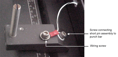
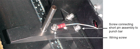
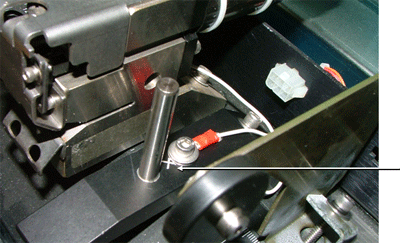
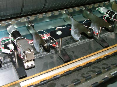
The short pin assembly was lengthened so that the small plate hits the short pin assembly and is guided into the punch, and an additional (outer) short pin assembly was added. | ||||||||||||||||||||
Time needed to implement |
1 hour |
||||||||||||||||||||
Parts needed |
Note: If your configuration requires only the outer pins, do not order this FCO; order shortcut pin assy-wide plate kit (part number 518-01144A) |
||||||||||||||||||||
Procedure |
|
||||||||||||||||||||
Test |
Using a small plate, perform the loading sequence and verify that the small plate touches the short pins as required. |
||||||||||||||||||||
Logistics |
Approved quantities:
| ||||||||||||||||||||
Material Disposition |
Dispose of the old short pin assembly (P/N 507A3E860). |
||||||||||||||||||||
Technical contact |
Product Support Manager: Haim Vaknin |
||||||||||||||||||||
Date submitted |
01 Sep 2002
Doc # 719-28818 Rev B |
||||||||||||||||||||