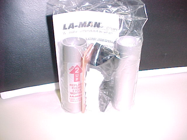
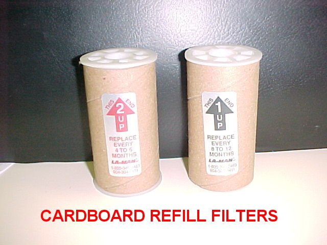
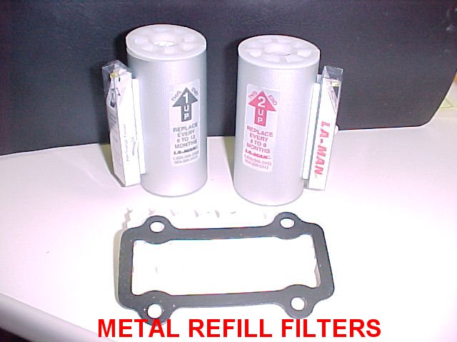
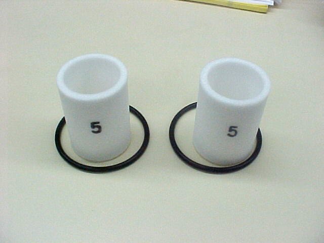
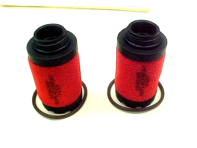
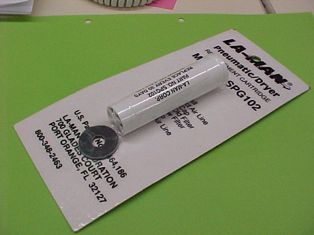
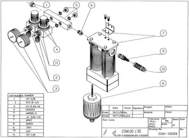
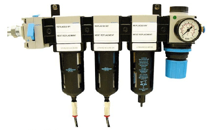
Replace filters every six months. See the PM part list above for filter part
numbers.
Click the relevant diagram or photo to enlarge.
PN 293B6B703
PN 510K1N007
PN 500-01720A
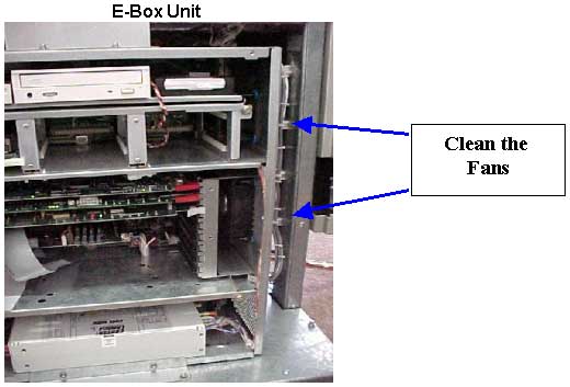
Fans - cleaning
Check that all the drum screws are secured with red paint, and that the
paint is not broken.
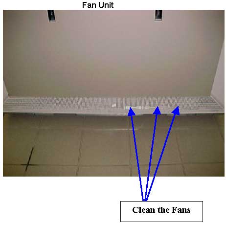
Clean all the Fans, as shown below.
Visually check the machine for any residue.
DETECTORS
Dust, especially ablation dust, coming from plate exposure can reduce detector
performance and reliability. The frequency of detector maintenance depends upon
machine use and plate type. (Kodak plate users should perform this procedure
more frequently.)
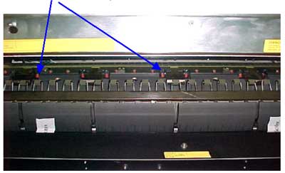
Clean the following detectors with rice paper and alcohol:
DRUM DETECTORS
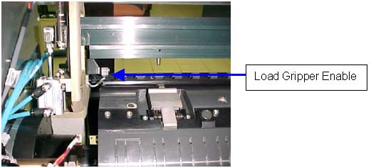
Load Gripper Enable Detector
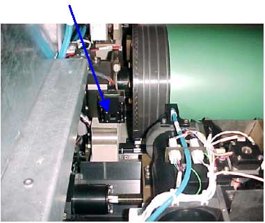
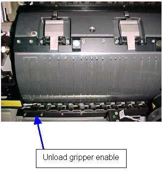
Unload Gripper Enable Detector
LASER SYSTEM
Light Detector (window).
AUTO LOADER LOADING SYSTEM
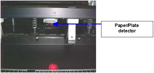
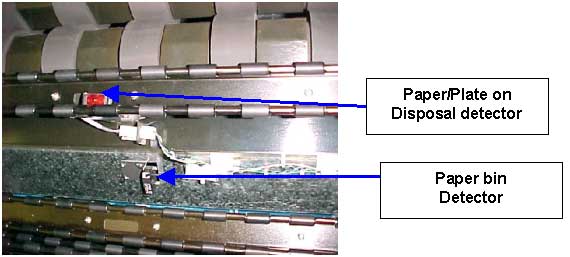
Paper / Plate on disposal
Paper / Metal detector
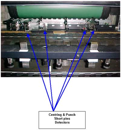
Centering short pins
Punch short pins
Paper bin detector
UNLOADING SYSTEM
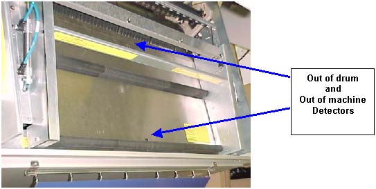
Plate out of drum detector
Plate out of machine detector.
LENS PROTECTOR
The frequency of lens protector maintenance depends on machine use and the
plate type. (Kodak plate users should perform this procedure more frequently.)
From the GUI, select Utilities>Hardware>Expose Eystem>Carriage
System
Double-click Carriage Motor.
In the Carriage Motor dialog box, run the carriage to end position (EP).
From the GUI, select Routine Function>Open Rear Door.
Shut down the machine.
Turn off the air supply to the machine.
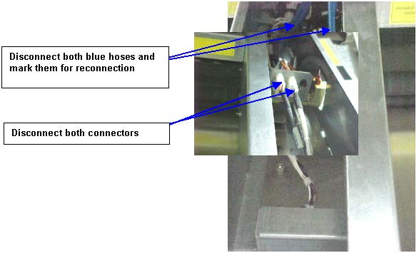
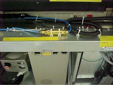
Disconnect both blue air hoses from the Plate Down valve in the unloading
assembly .
Disconnect both connectors from the right side of the assembly and one connector
from the left side of the assembly
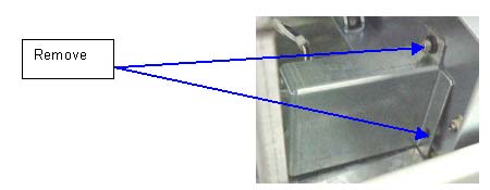
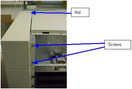
Disassemble the light cover (held by 2 screws).
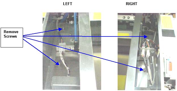
Release 4 screws (10x32) holding assembly 2 from each side.
Raise the left side of the assembly while paying attention to the motor
wiring on the right hand side. Pull the assembly out (left and then out).
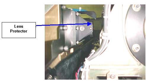
Do Not Remove The Lens Protector !!!
(Removing the lens protector may affect the focus).
Using rice paper (cleaning tissue) and alcohol, clean the lens protector.
Be careful not to scratch the lens protector.
Reassemble the unloading system connectors, hoses and covers
in reverse order to the way you disassembled them.
OP AIR SUPPLY (FUFU)
Replace the optic air supply (fufu) filter every 12 months.
Filter P/N - 342A10305.
Vacuum Pump
A clogged vacuum filter can reduce the amount of vacuum, and may cause problems
with
plate attachment to drum. Perform maintenance on the pump regularly to achieve
best operating results.
Maintenance intervals depend on the pump's use and ambient conditions.
Replace the filter every 12 months.
From the GUI, select Routine Function>Open Rear Door.
Shut down the machine.
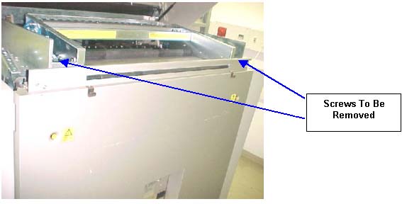
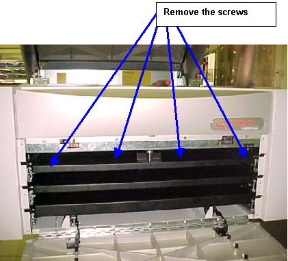
Remove the Back panel by releasing the 2 screws (10x32) as shown in the
picture below.
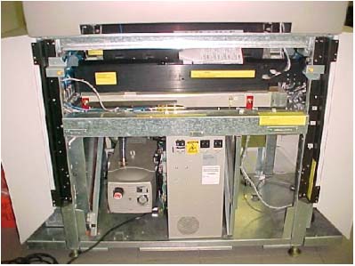
The Vacuum Pump is located at the bottom of the machine.
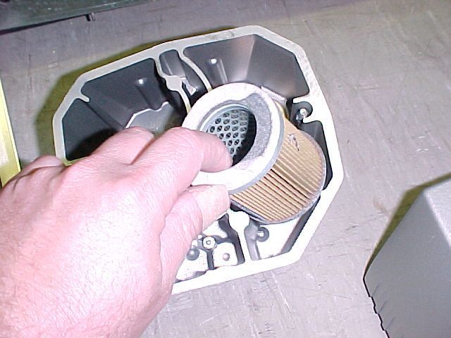
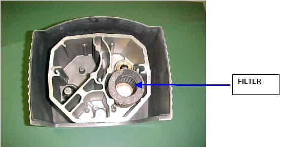
The filter cartridge is inserted behind the enclosure cover
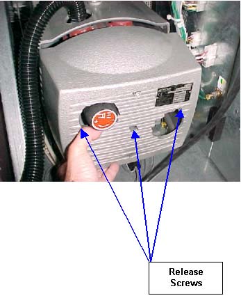
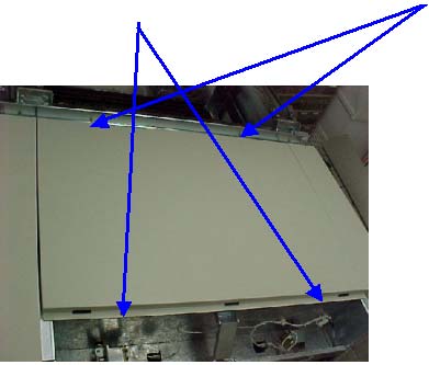
Remove the enclosure cover from the Vacuum pump by releasing the 3 screws
shown in the picture below.
Replace the filter.
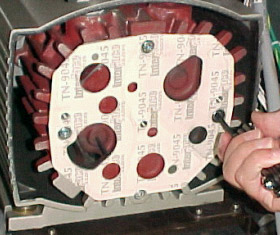
To check the vacuum pump blades, remove the blades cover by opening the
four Allen screws (see Figure 4).
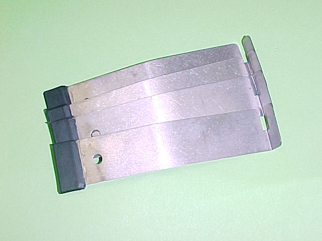
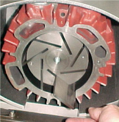
Pull out the seven vacuum pump blades one by one (see Figure 5).
Using an external air pressure hose, clean the inner areas of the vacuum
pump.
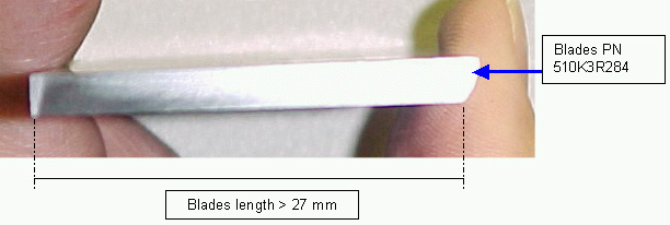
Measure the vacuum pump blades with a caliber. The width should be greater
than 27mm.
If the width of any of the vacuum pump blades is less than 27 mm, replace
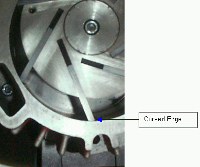
all the blades in the set with a new set (P/N 510K3R284). Important: Insert the vacuum pump blades with
the curved edge fitting into the housing curve (see Figure 7).
Secure the blades cover by tightening the four Allen screws.
Reassemble the parts in reverse order.
SWIVEL
From the GUI, select Routine Function>Open Rear Door.
Open the right side door
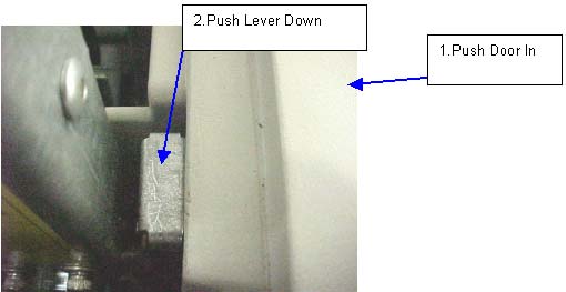
To open the door, press the latch down while pushing the door in, as shown
below.
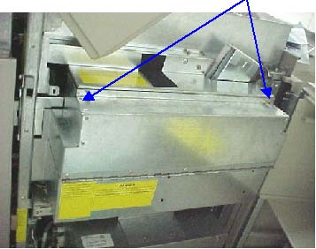
Open the right light cover held by 2 screws
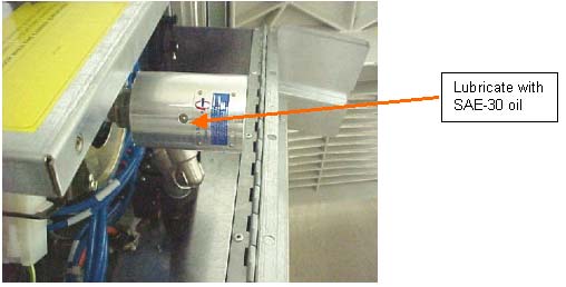
Lubricate the swivel with 4-5 drops of SAE 30 motor oil. Do this every 3
months.
Close the cover and the doors.
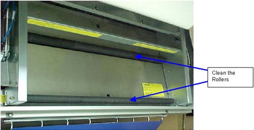
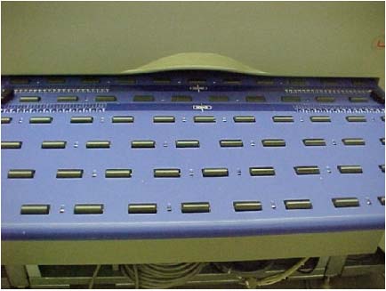
ROLLERS (Disposal, Loading, Unloading trays)
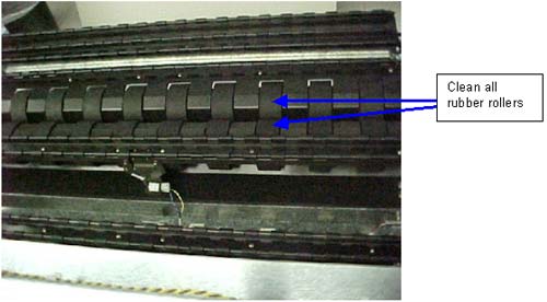
Clean all rollers with a clean cloth and Super Rubber Rejuvenator
DISPOSAL rollers (MCUR only)
UNLOADING SYSTEM rollers
LOADING TRAY rollers
Clean all of the rollers
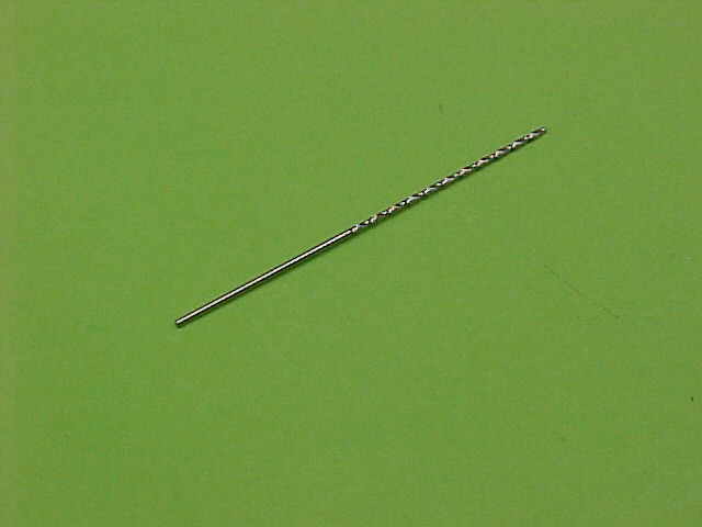
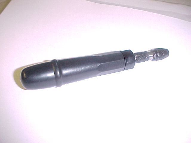
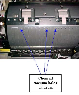
DRUM HOLES
Use the drill from the accessory kit to clean drum holes.
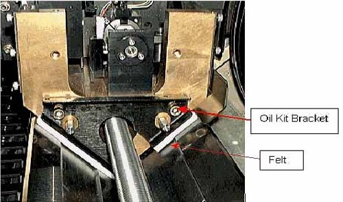
V BLOCK & FELT OILING
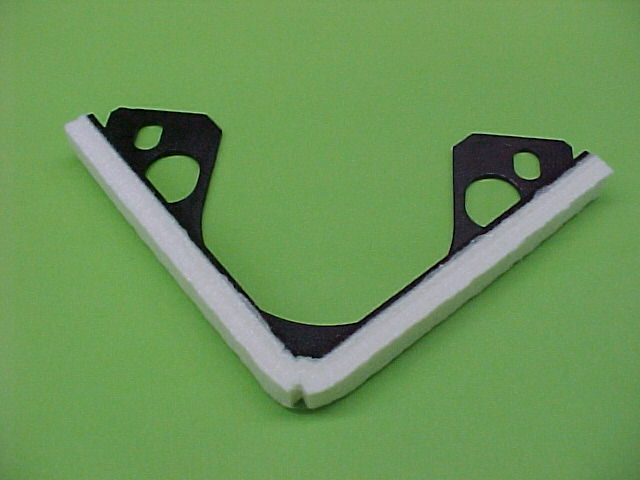
Oil Brackets
Lotem 400 and Lotem 400 Xpose (part number 252-08459A)
Lotem 400 Quantum (part number 291A5A397)
Silicon oil (part number 402-00172) order separately (for safety reasons,
oil is not shipped with the machine)
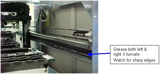
To apply oil to the felt:
Send the carriage to middle position.
Open the relevant doors and panels to allow access to the V-block.
If relevant, remove the unload tray.
Remove the four screws that secure the oil brackets (2 on each bracket)
and remove the oil brackets. Note: Keep the screws, they are used again later in
this procedure.
Dispose of the oil brackets.
Clean off any oil and dirt from the V-block.
Using 70% alcohol, clean the V-block to prevent ablation residue and dirt
from being absorbed into the oil.
In each new oil bracket, apply 3 cc silicon oil evenly along each felt. Note: Platesetters have four felts.
After applying the oil, allow the felt to absorb the oil for 2-5 minutes.
Insert the oil brackets, and insert, but do not tighten, the screws
that you removed in step 4. Note: Use Loctite® 242 on the screws.
Carefully push the brackets downward to allow the felt to be lightly
pressed against the V-block (or carriage beam).
Important: do not exert high force on the bracket.